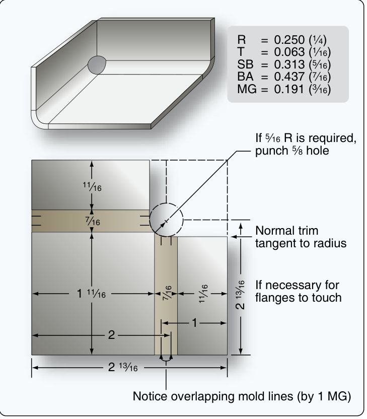
Where the deduction comes from
Where to buy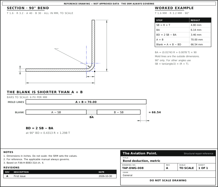
Bend deduction, 90° bend, mm
Sheet thickness T down the side, inside bend radius R across the top. The deduction is taken off the sum of the two outside (mold line) dimensions. These are not recommended radii: check the radius for your alloy in the bend radius chart.
| T \ R | R 1 | R 2 | R 3 | R 4 | R 5 | R 6 |
|---|---|---|---|---|---|---|
| 0.8 mm | 1.47 | 1.90 | 2.33 | 2.76 | 3.19 | 3.63 |
| 1.0 mm | 1.73 | 2.16 | 2.59 | 3.02 | 3.45 | 3.89 |
| 1.6 mm | 2.51 | 2.94 | 3.37 | 3.80 | 4.23 | 4.66 |
| 2.0 mm | 3.03 | 3.46 | 3.89 | 4.32 | 4.75 | 5.18 |
| 2.5 mm | 3.68 | 4.11 | 4.54 | 4.97 | 5.40 | 5.83 |
| 3.2 mm | 4.58 | 5.02 | 5.45 | 5.88 | 6.31 | 6.74 |
Calculated: BD = 2 (R + T) − (0.01743 R + 0.0078 T) × 90 = 0.4313 R + 1.298 T, millimetres in, millimetres out. Rounded to 0.01 mm.
How to use it, and where it comes from
Use. Add the outside dimensions of the part, subtract one deduction per bend, and you have the blank: blank = ΣMLD − ΣBD. The Handbook's own check applies: the blank must come out smaller than the sum of the mold lines (p. 4-67). Its J-chart gives the same quantity as the factor X (pp. 4-68 and 4-69).
Derivation. Setback is SB = K (R + T) with K = 1 at 90 degrees (p. 4-60). Bend allowance is BA = (0.01743 R + 0.0078 T) × N (p. 4-65). The metal in the bend is BA long where the two mold lines would run SB + SB, so the deduction is 2 SB − BA. At N = 90 that collapses to 0.4313 R + 1.298 T, which is why one table covers any alloy: the formula depends only on the radius and the thickness.
Metric is safe. The coefficients are per degree and carry no unit, so the formula holds in millimetres as it does in inches. The constant 0.01743 is almost π/180, and 0.0078 / 0.01743 is 0.45, which puts the neutral axis about 0.45 T in from the inside, close to the Handbook's 0.445 T (p. 4-64).
Worked example
An L-bracket in 1.6 mm sheet, inside radius 3.2 mm, outside dimensions A = 40 mm and B = 30 mm, one 90-degree bend.
- Setback: SB = R + T = 3.2 + 1.6 = 4.80 mm.
- Bend allowance: (0.01743 × 3.2 + 0.0078 × 1.6) × 90 = 6.14 mm.
- Deduction: 2 × 4.80 − 6.14 = 3.46 mm. The same from the shortcut: 0.4313 × 3.2 + 1.298 × 1.6.
- Blank: 40 + 30 − 3.46 = 66.54 mm.
Cut 66.54 mm. With the flats as a check: (40 − 4.80) + 6.14 + (30 − 4.80) = 66.54 mm.
Checked against the Handbook
The Handbook's J-chart examples are in inches, so they test the formula directly. Example 1 (R 0.22, T 0.063, 90°): the formula gives 0.177 in; the chart is read at 0.17 in. Example 2 (R 0.25, T 0.050, 45°, with SB = K (R + T), K = tan 22.5°): the formula gives 0.0349 in; the chart is read at 0.035 in (p. 4-69). A chart read by eye and the formula agree to the chart's reading accuracy.
The Handbook's U-channel gives the same result a third way: two 90° bends in 0.040 in sheet with R 0.16 in take 4.00 in of mold lines down to a 3.76 in blank (pp. 4-62 to 4-67).
Questions people actually ask
Does it work for 45° or 135° bends?
Not from this table. For another angle the setback is K (R + T) with K = tan (angle / 2), and the bend allowance uses N in degrees. The bend allowance calculator does both.
Why does my brake produce a slightly different length?
The formula carries an empirical neutral axis; your tooling, sheet temper and springback may differ. Bend a test strip and measure it. The calculator can calibrate against one.
Which dimensions do I subtract from?
The outside mold line dimensions, the ones to the sharp corner. If your drawing dimensions are to the inside, convert them first.
Limits — when NOT to use this chart
What the sources support, and no further.
- 90° bends only. Other angles need their own setback and allowance.
- A formula result, not a measured one. It is the Handbook's formula, not a manufacturer's table for a specific brake.
- Radius is not checked. Whether R is allowed for the alloy and temper is for the radius chart and the SRM.
Where to buy
Distributors coming soon.
Sources
- FAA-H-8083-31A, AMT Handbook: Airframe, Volume 1, Chapter 4 — p. 4-60 setback and K-factor; p. 4-64 neutral axis; p. 4-65 bend allowance formula; p. 4-67 total developed width; pp. 4-68 and 4-69 J-chart and examples.
- FAA AC 43.13-1B CHG 1, Chapter 4, par. 4-56 — setback, mold line dimension, and the 90 degree case SB = R + T.