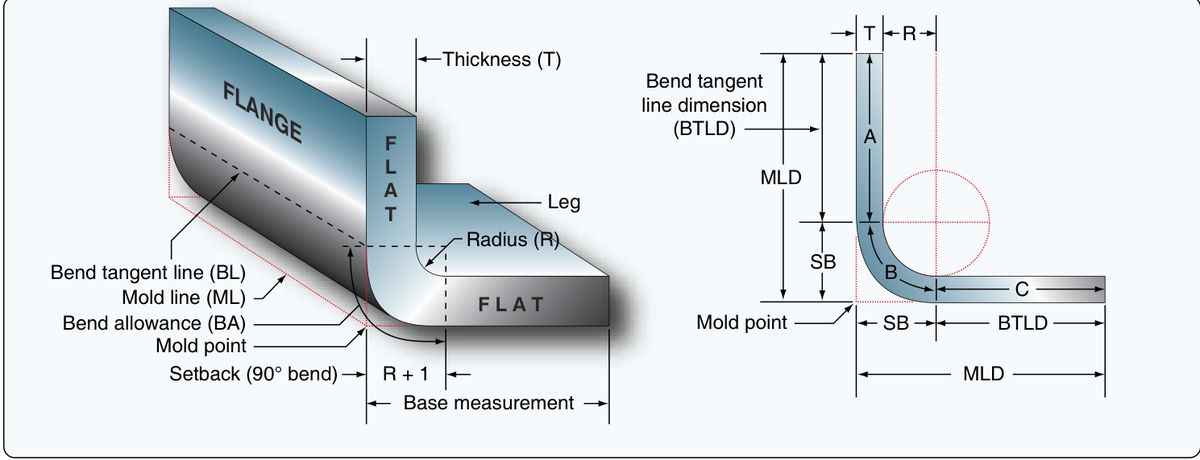
One bend, one blank, one corner
Where to buy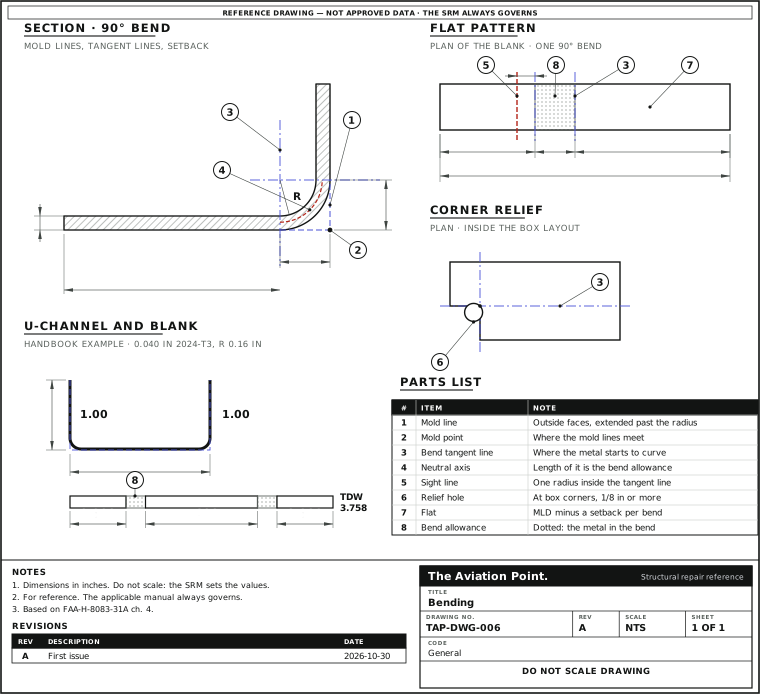
From drawing to blank, one step at a time
| Step | Action | What to do |
|---|---|---|
| 1 | Choose the radius | Take it from the drawing or the SRM. It sets everything after it. |
| 2 | Find the setback | It is how far the jaws sit back from the mold line. |
| 3 | Work out the flats | Take the setback off each flat. A flat with a bend at each end loses it twice. |
| 4 | Add the bend allowance | Each bend needs its own length of material. |
| 5 | Check the total | The blank must come out smaller than the sum of the mold lines. |
| 6 | Prepare the sheet | Smooth rough edges, remove burrs, and drill relief holes at the ends of bend lines and at corners. |
| 7 | Set up the brake | Draw the sight line, set the nose gap and test on scrap. |
The words and the formulas
| Term | What it is | Formula |
|---|---|---|
| Mold line dimension (MLD) | Size of the part to the intersection of the mold lines, as if the corner had no radius | From the drawing |
| Bend radius (R) | Measured to the inside surface of the metal | From the drawing or Table 4-6 |
| Setback (SB) | How far the brake jaws sit back from the mold line; also the distance from mold line to bend tangent line | SB = K (R + T) |
| K | One for 90 degrees; for any other bend, the tangent of half the bend angle | K = tan (angle / 2) |
| Flat | The straight part not in the bend | Flat = MLD − SB |
| Bend allowance (BA) | Length of the neutral axis through the bend, any bend 1 to 180 degrees | BA = (0.01743 R + 0.0078 T) × N |
| Total developed width (TDW) | The blank: flats plus bend allowances. It must be less than the sum of the MLDs | TDW = flats + BA × bends |
| Bend angle | Angle turned from flat, not the angle between the legs | 180° − angle between flanges |
FAA-H-8083-31A Vol. 1 pp. 4-59 to 4-67; bend allowance formula p. 4-65; AC 43.13-1B par. 4-55 and 4-56. R and T in inches, N in degrees.
Start with the radius
The radius sets everything after it, so choose it first. The minimum depends on the alloy, its temper and its thickness: thinner and softer sheet bends sharper. Annealed sheet can be bent to about its own thickness; 2024-T3 and stainless steel need a fairly large radius (Handbook p. 4-61).
Too tight and the outside of the bend cracks, sometimes in service rather than on the brake. AC 43.13-1B Table 4-6 gives recommended radii for aluminium; the bend radius chart has the whole table. A manufacturer's SRM chart can be stricter, and then it governs.
Before bending, smooth rough edges, remove burrs, and drill relief holes at the ends of bend lines and at corners. Lay bend lines at an angle to the grain, preferably 90 degrees (AC 43.13-1B par. 4-55).
Worked example: the Handbook's U-channel
0.040 in 2024-T3, mold lines 1.00, 2.00 and 1.00 in, two 90-degree bends (Handbook pp. 4-61 to 4-67).
- Radius: the Handbook takes 0.16 in from its manufacturer's chart.
- Setback: K = 1, so SB = 0.16 + 0.040 = 0.200 in.
- Flats: 1.00 − 0.200 = 0.800; the middle flat has a bend at each end, 2.00 − 2 × 0.200 = 1.600; 0.800.
- Bend allowance: (0.01743 × 0.16 + 0.0078 × 0.040) × 90 = 0.279 in each.
- TDW: 0.800 + 1.600 + 0.800 + 2 × 0.279 = 3.758 in, less than the 4.00 in of mold lines, as it must be.
Cut a blank 3.76 in wide. The Handbook rounds BA to 0.27 and prints 3.74 in; that is rounding, twice. For a bend that is not 90 degrees, the bend allowance calculator applies K = tan (angle / 2).
At the brake
Sight line. Draw it one bend radius inside the bend tangent line that goes in the brake, and set it even with the nose of the brake (p. 4-67). The nose radius bar sets the bend radius; a smaller bar can be built up with nose shims, each one adding its thickness to the radius (p. 4-70).
Set the brake for the sheet. Clamp pressure firm and even on both sides, no sponginess (p. 4-70). Nose gap: with the leaf held at the finished angle there is one material thickness between leaf and nose bar (p. 4-71).
Check it with scrap. Clamp two strips 3 in from each end of the brake, bend both 90 degrees and lay one on the other; they should match. If not, adjust the end with the sharper bend back slightly (pp. 4-71 and 4-72).
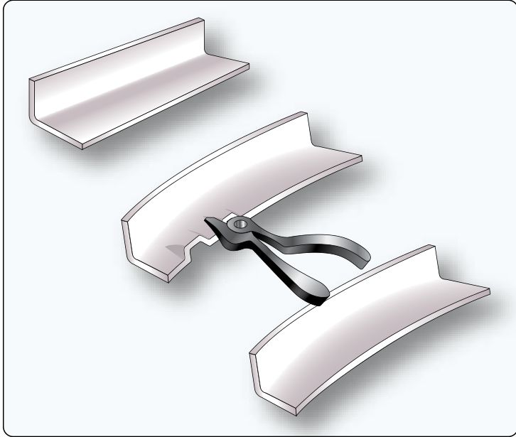
Corners need a relief hole
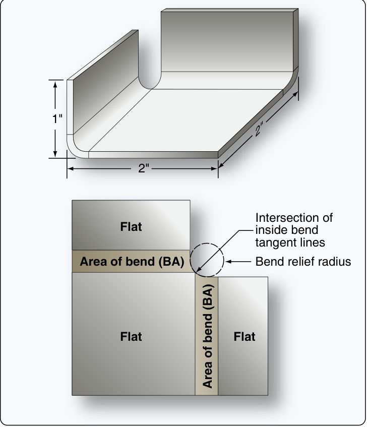
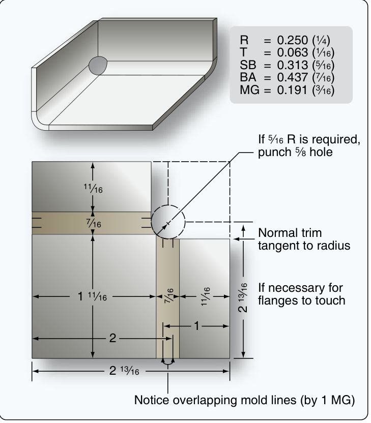
Where two bends meet, as in a box or pan, the bend allowance areas would run into each other and the corner tears. A relief hole drilled or punched at the intersection of the inside bend tangent lines removes that material.
Place the hole so its edge touches the intersection of the inside bend tangent lines; allow it to reach 1/32 to 1/16 in behind those lines for bending error. Handbook minimum: 1/8 in diameter in aluminium sheet up to 0.064 in thick. The drawing normally gives the radius; the larger and smoother the hole, the less likely a crack at the corner (pp. 4-72 and 4-73).
If it goes wrong
| You see | Look first at |
|---|---|
| Blank longer than the sum of the MLDs | The arithmetic: TDW must come out smaller, because the metal follows the radius (p. 4-67) |
| Crack across the outside of the bend | Radius below the minimum for the alloy and temper (p. 4-61, AC par. 4-55) |
| Corner tears or buckles in a box | Missing or undersized relief hole (pp. 4-72, 4-73) |
| Bend angle differs along the brake | Nose gap and clamp pressure; compare the test strips (pp. 4-71, 4-72) |
| A flat the wrong length | A bend not counted at both ends of a flat; the middle flat of a channel loses two setbacks (p. 4-64) |
Causes as the Handbook states them; the part's drawing and the SRM decide the repair.
Questions people actually ask
Is the neutral axis at mid-thickness?
Not exactly. The Handbook puts it about 0.445 times the thickness from the inside of the bend (p. 4-64), and says that assuming the centre is satisfactory for most work (p. 4-59). The bend allowance formula already carries an empirical value.
Which angle goes in the formula?
The angle turned from flat. Flanges drawn 120 degrees apart make a 60-degree bend: 180° minus the angle between the flanges (p. 4-65).
Radius to the inside or the outside?
The inside surface. Both AC 43.13-1B (par. 4-55) and the Handbook (p. 4-59) define it so.
Can I use a setback chart or the J-chart instead?
Yes. The Handbook shows both, and says the J-chart is not as accurate as the layout method but enough for most applications (p. 4-67).
Limits of this guide
What the sources support, and no further.
- Radius and angle come from the drawing or the SRM. Table 4-6 is a recommendation for aluminium, not a limit for a repair.
- Hot forming, stainless, titanium and magnesium are not covered here.
- Springback is not modelled. Test on scrap of the same sheet.
Where to buy
Distributors coming soon.
Sources
- FAA-H-8083-31A, AMT Handbook: Airframe, Volume 1, Chapter 4 — pp. 4-59 to 4-60 terminology, K-factor, setback, flat, TDW; p. 4-61 radius; pp. 4-62 to 4-67 U-channel layout, setback, bend allowance (formula p. 4-65), sight line (p. 4-67); pp. 4-68 and 4-69 J-chart; pp. 4-70 to 4-72 brake setup; pp. 4-72 and 4-73 relief holes.
- FAA AC 43.13-1B CHG 1, Chapter 4, par. 4-55 and 4-56 — bend radius to the inside, Table 4-6, burrs, relief holes, grain direction, setback and mold line.