Insertion, section, patch limits and frame
Where to buy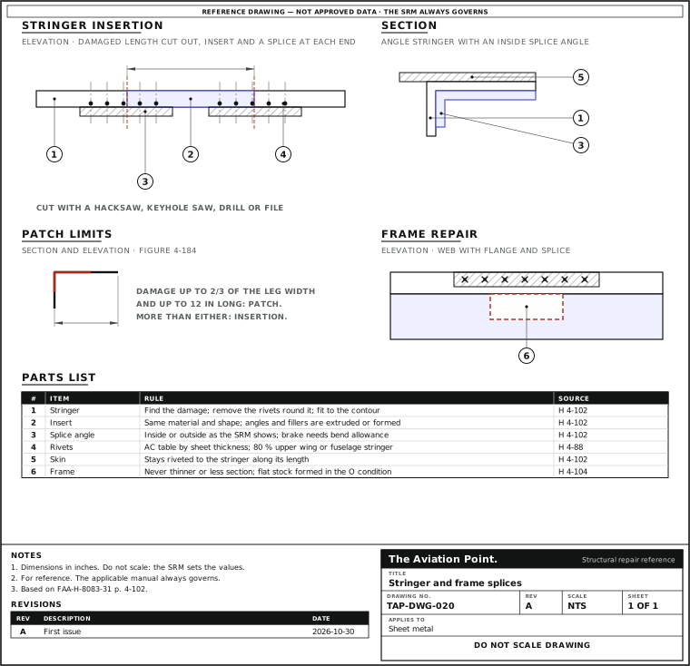
Splice a stringer, one step at a time
| Step | Action | What to do |
|---|---|---|
| 1 | Find the extent | Find how far the damage goes and remove the rivets round it. |
| 2 | Cut it out | Use a hacksaw, keyhole saw, drill or file. |
| 3 | Make the parts | Make the insert and the splice angle from extrusions or preformed material where available. |
| 4 | Fit the splice angle | It goes inside or outside the stringer, as the SRM shows. |
| 5 | Drill and rivet | Drill through the splice and stringer, deburr, protect the contact faces and rivet. Check the result against the SRM. |
Patch, or insertion
| Damage | Repair | Source |
|---|---|---|
| Up to 2/3 of one leg's width and 12 in long | Patch | H 4-102, fig. 4-184 |
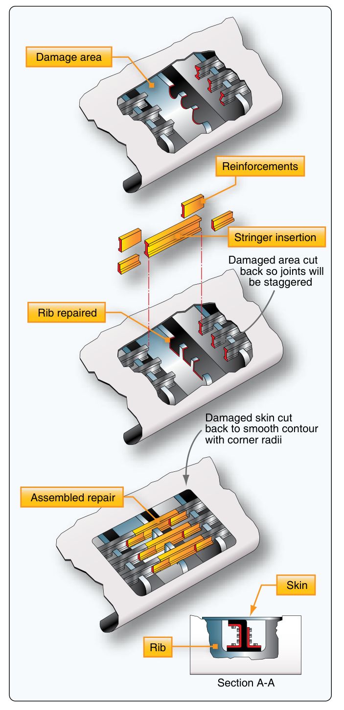
| More than 2/3 of one leg, part of the stringer removed | Insertion | H 4-102, fig. 4-185 |
| One stringer, more than 12 in long | Insertion | H 4-102, fig. 4-186 |
| More than one stringer, over 12 in | Insertion across the stringers | H 4-102, fig. 4-187 |
| Longeron | As a stringer, with heavier rivets, pitch 4D to 6D | H 4-104 |
H = FAA-H-8083-31 Vol. 1 page. The SRM sets the repair for each stringer.
Order of work
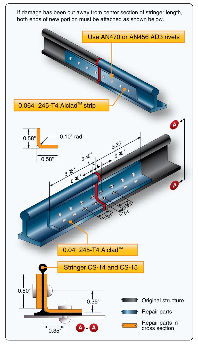
1. Find the extent of the damage and remove the rivets round it. 2. Cut the damaged part out with a hacksaw, keyhole saw, drill or file. 3. Make the insert and the splice angle from extrusions or preformed material where available. If they come from flat sheet, use the brake, with bend allowance and sight lines for the layout: the bend allowance calculator does it (H 4-102).
4. Fit the splice angle inside or outside the stringer as the SRM shows: some repairs go inside, some outside. For a curved stringer make the parts to the original contour (H 4-102).
5. Drill through the splice and stringer, deburr, protect the contact faces, rivet. Check the result against the SRM.
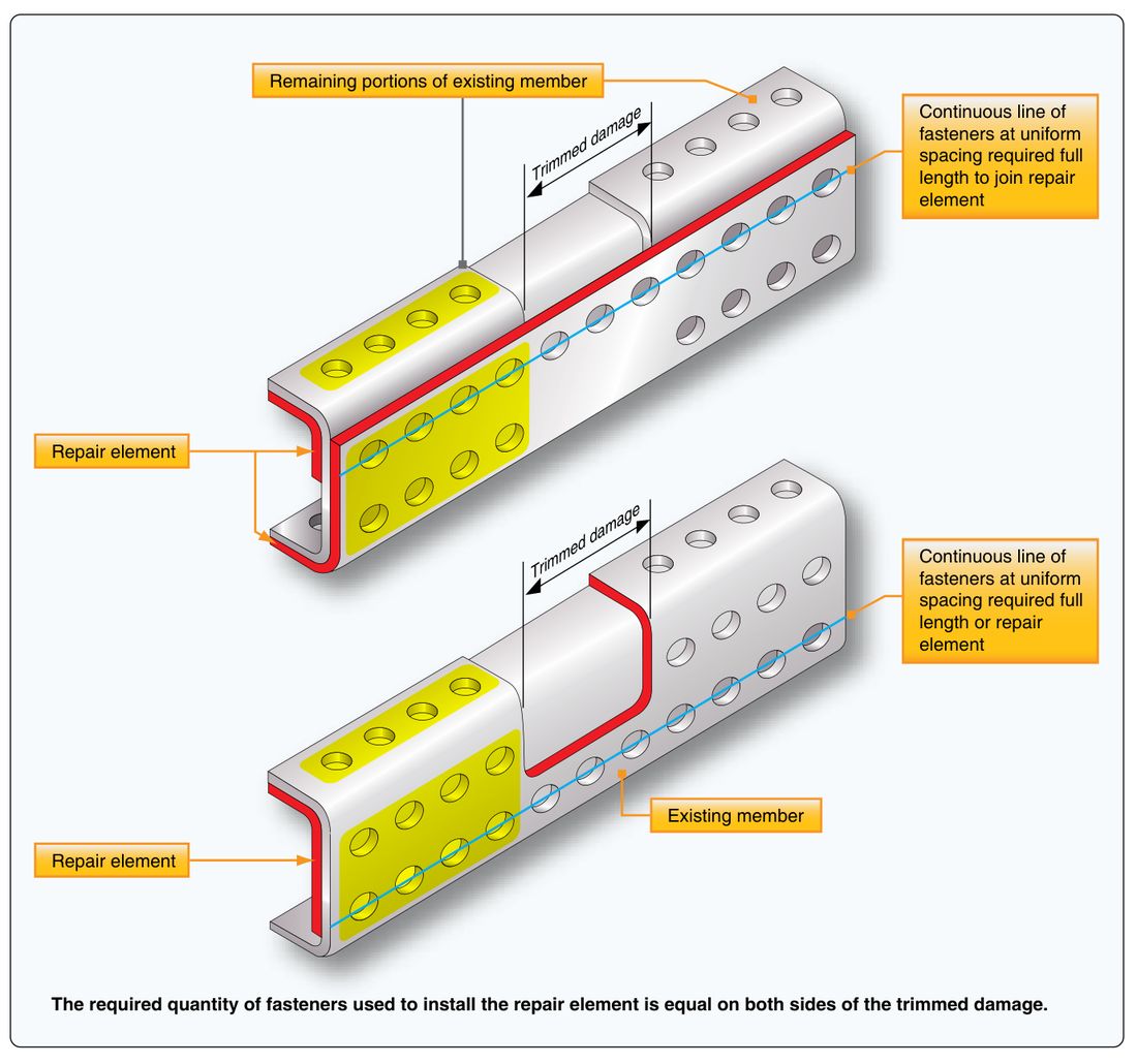
Rivets each side of the cut
The number comes from the SRM, or from the AC table of rivets per inch of width by sheet thickness and rivet size (H 4-88, fig. 4-169). The table's notes allow 80 % of that number for a stringer in the upper surface of a wing or in a fuselage, 60 % for intermediate frames and 75 % for single-lap sheet joints. Check shear and bearing in the rivet strength calculator.
Longerons are heavier members: heavier rivets, pitch 4D to 6D, and bolts only where needed, drilled for a light drive fit. Treat a formed section and an extruded angle separately (H 4-104).
Frames and bulkheads. Damage is classified like any other, and specifications come from the maker. Repair parts from flat sheet must give the original tensile, compressive, shear and bearing strength; never use thinner material or less cross-section. Curved parts are formed in the O condition and heat treated before installation (H 4-104).
Questions people actually ask
Inside or outside splice angle?
Whichever the SRM shows for that stringer: the Handbook says some are repaired inside, others outside (H 4-102).
How long may a stringer patch be?
Up to 12 in, with damage no more than 2/3 of one leg's width; beyond that, insertion (H 4-102).
Can the insert be a different alloy?
Not freely: the insert is the same material and shape. Any substitution follows the SRM and the principles guide (H 4-102, 4-93).
How many rivets each side?
The SRM gives it. The AC table gives a starting count, reduced as its notes allow (H 4-88).
Limits of this guide
What the sources support, and no further.
- No splice length is given. The sources do not state one; it follows from the rivet count and the SRM.
- Typical only. Handbook figures give example dimensions for one stringer, which are not copied here.
- Primary structure such as spars needs the manufacturer's data.
Where to buy
Distributors coming soon.
Sources
- FAA-H-8083-31, AMT Handbook — Airframe, Volume 1, Chapter 4 — p. 4-88, fig. 4-169, rivet table and notes; p. 4-102, stringer repair; p. 4-104, longeron and bulkhead repair.