Flush and lap patch, view by view
Where to buy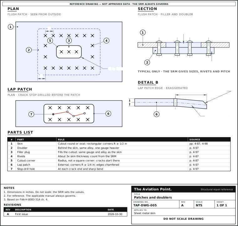
Build a patch, one step at a time
| Step | Action | What to do |
|---|---|---|
| 1 | Stop any cracks | Drill a small stop hole at each end and each sharp bend before the patch goes on. |
| 2 | Get the sizes | Take the size, rivet and pitch from the SRM. |
| 3 | Fit the patch | Chamfer the edge and bend it down over the edge distance, so it seals. |
| 4 | Drill | Drill one hole and fasten it. Find the second with a hole finder, then drill the rest through the original holes. |
| 5 | Prepare to rivet | Deburr the holes and put corrosion-protective material on the touching faces. |
Lap or flush
| Lap (scab) | Flush | |
|---|---|---|
| Where | Aerodynamics not critical | Smooth skin needed |
| Patch | External, overlaps the skin | Filler in the cutout plus an inside doubler |
| Material | Same alloy as the skin; the SRM sets the gauge | Filler: same gauge and alloy. Doubler: one gauge heavier |
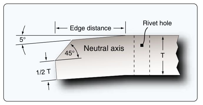
| Corners | Radius 1/4 in or more; edge chamfered 45 degrees for half the thickness, bent down 5 degrees | Cutout corners 1/2 in or more |
FAA-H-8083-31A pp. 4-87 and 4-97 to 4-98, Figs. 4-174 to 4-177.
Keep the original strength
Cross-section. The splice or patch must have at least the cross-sectional area of the damaged part. Avoid abrupt changes of section, and taper splices.
Outside or one gauge up. If the member is in compression or bending, the patch goes outside it. If it cannot, use material one gauge thicker than the original.
Cutouts. Make them round or oval. A rectangular cutout needs corner radii of at least 1/2 in, because cracks start from corners.
Similar material. A weaker alloy needs more thickness. A stronger, thinner one is not an equal swap: buckling and torsional strength follow thickness. The SRM gives the substitution.
Not too strong. A repair that is too stiff makes the skin flex at its edge and speeds up fatigue.
A buckled member is not trusted to carry load again however well it is reinforced: replace it or splice over it.
Rivet size and count
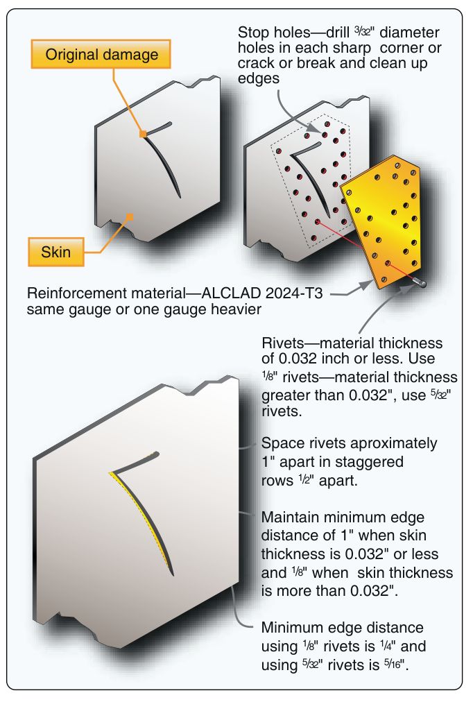
Size from the manufacturer's next parallel row inboard on a wing or forward on a fuselage, or about three times the skin thickness, rounded to the next size up. For 0.040 in skin, 3 x 0.040 is 0.120 in, so 1/8 in. The number comes from the SRM or from the AC 43.13-1B tables.
The AC's own example (4-58g): clad 2024 sheet 0.032 in, 10 in wide, 1/8 in AD rivets, 4.9 per inch of width times 0.75 gives 37 rivets, laid as two rows of 19. Count yours in the doubler calculator.
Edge distance at least 2D and pitch typically 4D to 6D for a non-pressurised patch (Handbook p. 4-98); see the layout guide.
Countersunk holes that must go oversize can take NAS1097 reduced-head rivets, which have the head one size smaller than the shank (a distributor's listing), if the manual or engineering authorises it.
Building it
Cracks. Drill a small stop hole at each end and each sharp bend before the patch goes on, to stop it spreading.
Fit. Chamfer the patch edge 45 degrees for half the thickness and bend it down 5 degrees over the edge distance so it seals. Drill one hole, fasten it, find the second with a hole finder, then drill the rest through the original holes.
Before riveting: deburr the holes and put corrosion-protective material on the touching faces (Handbook p. 4-99).
Questions people actually ask
Why one gauge heavier for the doubler?
It gives the load path margin round the hole. It is the usual rule for the doubler of a flush patch; the SRM may say otherwise.
Lap patch on a pressure skin?
The sources treat the non-pressurised case. For pressurised skin, use the SRM repair.
When is it a replacement instead?
When too many earlier repairs sit in one panel, or the damage exceeds the repairable limits: replace the panel (Handbook p. 4-99).
Limits of this guide
What the sources support, and no further.
- No patch size is given here. Size, rivet and pitch come from the SRM.
- Typical only. The Handbook figures are examples, not authority.
- Not pressurised skin or primary structure without the manufacturer's data.
Where to buy
Distributors coming soon.
Sources
- FAA-H-8083-31A, AMT Handbook — Airframe, Volume 1, Chapter 4 — p. 4-87, maintaining original strength, rivet size; pp. 4-97 to 4-98, patches, Figs. 4-174 to 4-177, design of a patch for a non-pressurised area; p. 4-99, panel repair and corrosion protection.
- FAA AC 43.13-1B CHG 1, Chapter 4 — par. 4-58f, patching of small holes; par. 4-58g, example (pp. 4-26 and 4-27).