The layout, view by view
Where to buy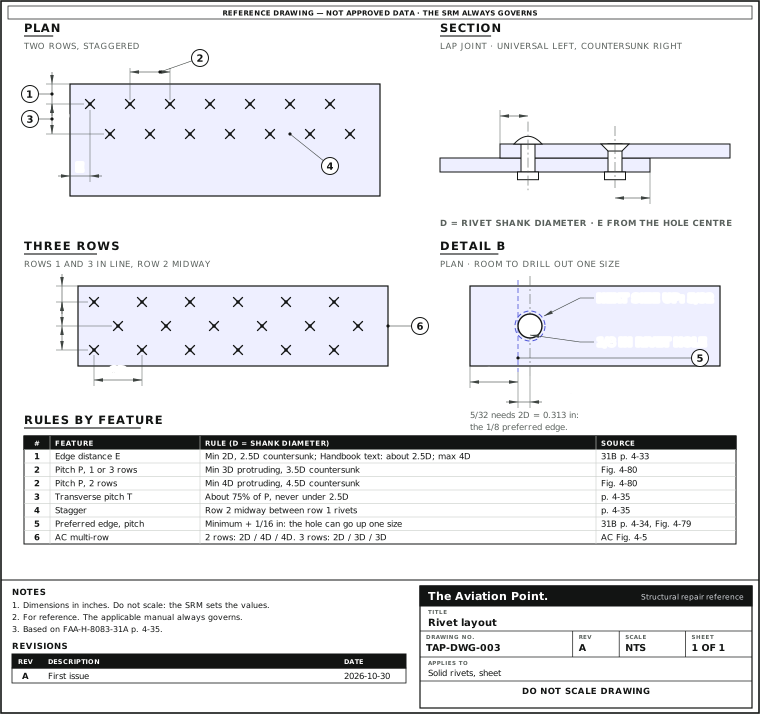
Lay out a run, one step at a time
| Step | Action | What to do |
|---|---|---|
| 1 | Copy the original | Unless structural deficiencies are suspected, duplicate the original spacing and edge distance. |
| 2 | Set the ends | For a new run, set the edge distance at each end of the row. |
| 3 | Lay off the pitch | Space the rivets between the two ends. |
| 4 | Add a second row | Place it one transverse pitch from the first, with its rivets midway between those of the first row. |
| 5 | Check against the SRM | Where sources differ, the aircraft's SRM governs. |
The minimums, in diameters
| Feature | Protruding head | Countersunk |
|---|---|---|
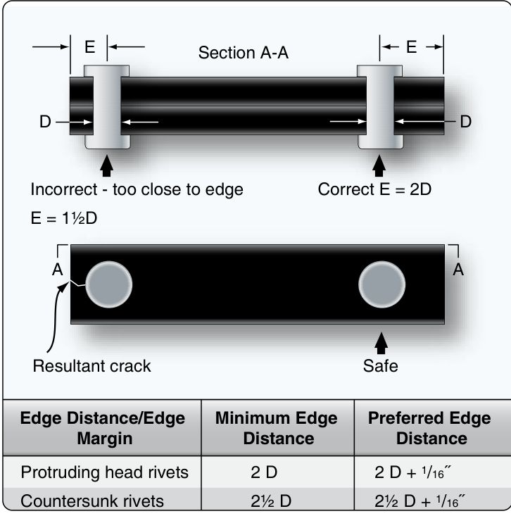
| Edge distance, minimum | 2D | 2.5D |
| Edge distance, maximum | 4D | 4D |
| Pitch, one or three rows | 3D | 3.5D |
| Pitch, two rows | 4D | 4.5D |
| Usual pitch | 4D to 6D, up to 10D | Larger than protruding |
| Transverse pitch | About 75% of pitch, never under 2.5D | Same |
FAA-H-8083-31A pp. 4-34 and 4-35 (Figs. 4-79 and 4-80). The figure prints the countersunk pitch as 3/1/2D and 4/1/2D, read here as 3.5D and 4.5D. Compute your own in the rivet-spacing calculator.
How to lay out a run
Copy the original first. AC 43.13-1B 4-57c: unless structural deficiencies are suspected, rivet spacing and edge distance should duplicate the original structure. The Handbook says the same for most repairs, and sends you to the SRM.
A new run. Set the edge distance at each end of the row, then lay off the pitch between them. For two rows, place row 2 one transverse pitch from row 1 and put its rivets midway between those of row 1. For three, lay off rows 1 and 3, then use a straightedge to find the spots in row 2.
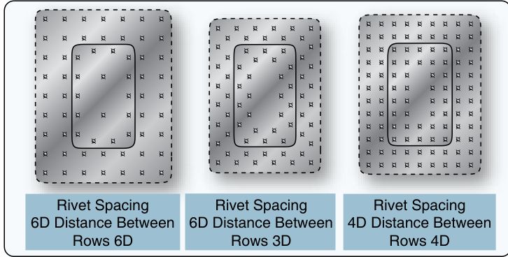
Rows of a single-lap splice. AC 43.13-1B Fig. 4-5: two rows at 4D pitch, 4D between rows, 2D edge distance (75% of the sheet's strength left through the row); three rows at 3D between rows, 6D pitch in each row, 2D edge (83%).
Tube splices. With rivets through the tube, space them 4D to 7D apart if adjacent rivets are at right angles and 5D to 7D if parallel, and keep the first rivet at least 2.5D from the end of the sleeve (Handbook p. 4-35).
Leave room to drill out
Add 1/16 in to the minimum edge distance and to the minimum pitch, or work them out with the next rivet size. A hole that later needs the next size up then still meets the minimum. A 1/8 in rivet at 2D plus 1/16 sits 0.313 in from the edge, which is exactly the 2D of a 5/32 in rivet.
The Handbook gives two figures for the edge. Its text recommends about 2½ rivet diameters (31B p. 4-33); Fig. 4-79 and its worked example call the minimum + 1/16 in the preferred edge distance (31B p. 4-34). The two meet only on a 1/8 in protruding-head rivet. On a countersunk head 2.5D is the minimum itself, so this site lays out to the minimum + 1/16 in, as the edge distance calculator does.
Too close to the edge and the sheet cracks or pulls away from the rivets; too far and the edge turns up. Rivets nearer the minimum pitch suit parts in bending, where the skin between rivets can buckle.
Where the sources differ
| Source | Pitch minimum | Note |
|---|---|---|
| Handbook, Fig. 4-80 | 3D (1 and 3 rows), 4D (2 rows) | Countersunk 3.5D and 4.5D |
| Handbook, text p. 4-34 | 3.5D protruding, 4D flush | Not the same as the figure |
| Handbook, bullet p. 4-34 | 3D for new sections | Edge 2D, rows 2.5D |
| AC 43.13-1B 4-57c | 3D, single row | Edge 2D; Fig. 4-5 for more rows |
Where they differ, the aircraft's SRM or drawing decides. The calculators check against Fig. 4-80.
Questions people actually ask
Measured to the hole edge or the centre?
The centre. Measuring from the hole edge understates edge distance and pitch by half a diameter and a full diameter.
Which minimum do I use for a countersunk rivet?
2.5D edge and 3.5D or 4.5D pitch from Fig. 4-80, but the SRM first. The sheet must also be thick enough for the dimple or the countersink.
Can I use these for blind fasteners?
No. Cherry, Hi-Lok and lockbolt spacing comes from the manufacturer's data.
Limits of this guide
What the sources support, and no further.
- Minimums, not targets. The sources say so: they are general practice for solid aluminium rivets in sheet.
- No pressure skin, fuel tank or fatigue rules here. Those come from the SRM.
- The sources disagree in places; the table shows how.
Where to buy
Distributors coming soon.
Sources
- FAA-H-8083-31A, AMT Handbook — Airframe, Volume 1, Chapter 4 — p. 4-34, rivet spacing, edge distance, Figs. 4-78 and 4-79; p. 4-35, rivet pitch, transverse pitch, layout example, tube splice, Figs. 4-80 and 4-81.
- FAA-H-8083-31B, AMT Handbook — Airframe, Volume 1, Chapter 4 — p. 4-33, recommended edge distance about 2½ rivet diameters; p. 4-34, Fig. 4-79, the minimum + 1/16 in as the preferred edge distance.
- FAA AC 43.13-1B CHG 1, Chapter 4 — par. 4-57c, edge distance and spacing (p. 4-19); Figure 4-5, double and multiple row splices (p. 4-20).