Joggle, relief hole and lightening hole
Where to buy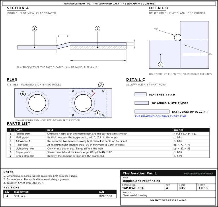
Form a joggle at the brake
| Step | Action | What to do |
|---|---|---|
| 1 | Find the sizes | The depth is set by the material to be cleared. The allowance is normally on the drawing. |
| 2 | Mark the bend lines | Mark both lines on the straight flange or flat piece. |
| 3 | Make the first bend | Bend up slightly on the first line. |
| 4 | Turn the part over | Clamp at the second line and bend until the joggle has its height. |
| 5 | Check | Check the dimensions and the clearance. |
The joggle
A joggle is an offset formed in a part so it clears a sheet or another member and the joint or splice stays smooth. It is common where stringers meet formers (Handbook p. 4-81).
Depth is set by the thickness of the material to be cleared, and is usually given in thousandths of an inch. Length: add an extra 1/16 in so the overlapped part fits. Allowance is the distance between the two bends, and is normally on the drawing.
Rule of thumb when it is not: four times the displacement for flat sheet; slightly more for a 90 degree angle because of the stress at the radius; up to 12 times the material thickness for extrusions. So follow the drawing. The joggle calculator works it out.
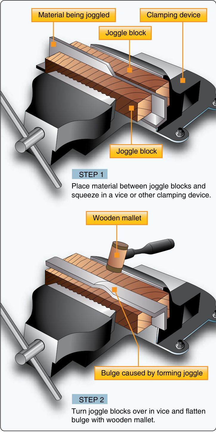
Forming. On a straight flange or flat piece, use a cornice brake: mark the bend lines, bend up about 20 to 30 degrees, turn the part over, clamp at the second line and bend until the joggle has its height, then check dimensions and clearance (p. 4-82). Curved parts go between joggle blocks or dies in a vice. Hardwood dies suit a few parts; aluminium dies are preferred for a run. Test new dies on waste stock first.
The metal stretches between the bends (p. 4-74). A hard temper may crack there: see the bend radius chart.
Relief holes
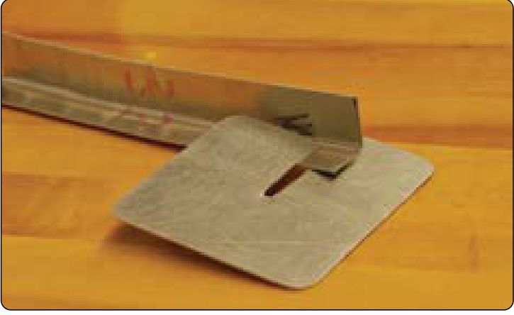
When a part has bends that cross, as in a box, material must be removed to make room for the flanges. A hole at the crossing of the inside bend tangent lines relieves the stress and stops tearing, and gives a clean corner to trim to (Handbook p. 4-72).
Size. No smaller than 1/8 in diameter for aluminium sheet up to and including 0.064 in. A larger minimum applies to 0.072 to 0.128 in sheet; the Handbook misprints that figure (3/160 in), so take it from the drawing. Often the bend radius is used for the hole, if it is not less than the 1/8 in minimum; the drawing normally specifies the radius. The larger and smoother the hole, the less likely a crack (p. 4-73).
Position. The hole's outer edge touches the crossing of the inside tangent lines, so no material interferes with the bend allowance of the other bend. If the two allowance areas overlapped, compressive stress would build in the corner and could crack the part in the brake. Allow 1/32 to 1/16 in beyond the tangent lines for bending error (p. 4-73).
Layout. Find the crossing of the inside tangent lines, bisect them, and move outward along the bisector by the hole radius: that is the centre. Drill, then trim off the rest of the corner. Where the corner is to be welded, the flange is one thickness short so that only the insides touch.
Lightening holes
The Handbook calls them "lightning holes"; they are cut in ribs, frames and other parts to save weight. A pressed flange around the hole stiffens the web that remains (pp. 4-82 to 4-83).
Only where authorised. Never cut one in structure unless the design allows it. Hole size and flange width come from the design specification, which includes the margin of safety. Cut with a hole saw, punch or fly cutter; file the edges smooth so they do not crack or tear.
Flanging. Use a female and a male die, or wood or metal form blocks; the pilot is the size of the hole and the shoulder the width and angle of the flange. Hardwood dies serve for soft metal and steel for hard metal or long runs. A light coat of machine oil helps.
Cracks round a flanged hole get a repair plate: stop-drill the crack or remove the damage, make the plate of the same material and thickness, rivet as the surrounding structure, edge distance at least 2D and pitch 4D to 6D (p. 4-99). Size the rivets in the rivet spacing calculator.
Questions people actually ask
Which sheet is the Handbook rule for allowance?
Flat sheet. Angles need slightly more and extrusions as much as 12 times the thickness, so the drawing decides.
Is a hole bigger than the minimum always better?
Larger and smoother helps avoid cracks (p. 4-73), but the hole must still fit the flat and the drawing.
Can I add a lightening hole to save weight?
Not unless authorised by the design data. The weight saved has been traded against strength in the specification.
Limits of this guide
What the sources support, and no further.
- No joggle depth or hole size is given beyond the Handbook minimums; the drawing sets them.
- Aluminium sheet. The relief hole minimums are for aluminium alloy stock.
- Repair plates follow the SRM where it gives the repair.
Where to buy
Distributors coming soon.
Sources
- FAA-H-8083-31A, AMT Handbook — Airframe, Volume 1, Chapter 4 — pp. 4-72 to 4-73, relief holes, location and layout, Figs. 4-145 and 4-146; p. 4-74, stretching in joggling; p. 4-81, joggling depth, length, allowance; p. 4-82, brake procedure, Fig. 4-163; pp. 4-82 to 4-83, lightening holes and flanging, Fig. 4-165; p. 4-99, repair of lightening holes.