Which brake
Where to buy| Machine | What it does | Limit in the Handbook |
|---|---|---|
| Bar folder | Turns edges; bend only as wide as the jaws are deep | Narrow work (H-31 p. 4-21) |
| Cornice brake | Folds sheet through the jaws front to rear without obstruction | 12 to 22 gauge, 3 to 12 ft long (p. 4-21) |
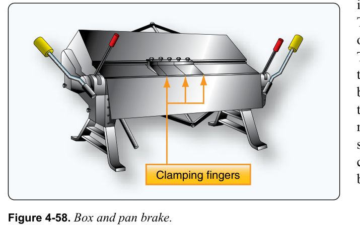
| Box and pan (finger) brake | As a cornice brake, plus boxes and pans: remove the fingers in the way | Check every remaining finger is seated and tight (p. 4-22) |
| Press brake | Heavier and more complex parts, hat channels, with gooseneck or offset dies | Cornice and box brakes top out near 0.090 in annealed aluminum, 0.063 in 7075-T6 or 0.063 in stainless (p. 4-22) |
H-31 = FAA-H-8083-31B, Airframe Handbook, Chapter 4. The brake's own capacity is set by its maker.
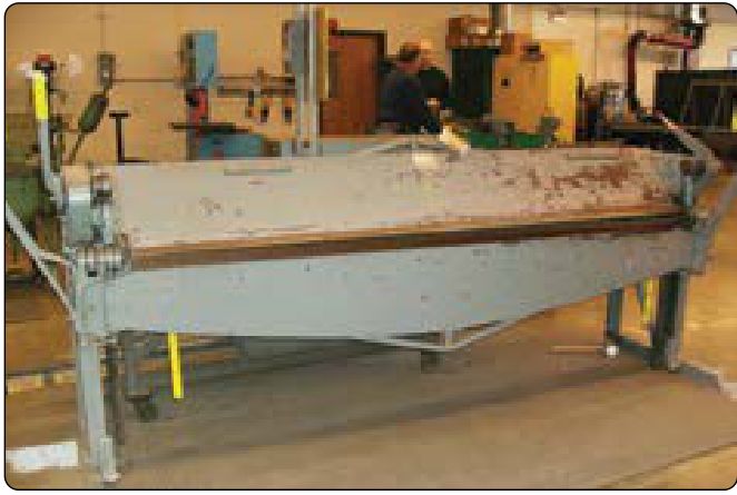
Make a bend
| Step | Action | What to do |
|---|---|---|
| 1 | Check the bend | Is the radius allowed for the alloy and temper? Check the bend radius chart and compute the flat length with the bend allowance calculator. |
| 2 | Mark the sight line | The line of the bend, drawn on the sheet. |
| 3 | Place under the bar | Sheet on the bed, sight line directly under the edge of the clamping bar. Bring the bar down to hold it firmly. |
| 4 | Set the stop | Set the stop at the right side for the angle, adding the spring-back: about 93 degrees to get 90. |
| 5 | Bend | Raise the bending leaf until it strikes the stop. |
| 6 | Next bend | Lift the clamping bar, move the sheet to the next position, repeat. |
| 7 | Check | Check the angle and the radius against the drawing, on a test piece first if the part is costly. |
Typical mistakes
| Mistake | What happens | Fix |
|---|---|---|
| Setting exactly 90 degrees | Part opens to 87 or 88 degrees | Set about 93 degrees (spring-back, p. 4-22) |
| Fingers not tight on a finger brake | Fingers shift during the bend | All unremoved fingers securely seated and tightened |
| Radius too tight for the temper | Cracks along the bend | Check the minimum bend radius chart |
| Thick stock on a light brake | Beyond capacity, damage | Capacity is set by the maker; use a press brake for thicker parts |
| Nose radius of the fingers too small | Wrong inside radius | Nose radius shims, made to the bend length (p. 4-22) |
Care
Keep the bed, bar and leaf clean and free of chips, or they mark the sheet. Lubrication, adjustment and calibration follow the machine maker's manual; the Handbook gives none.
Questions people actually ask
How much spring-back should I allow?
The Handbook's example: a cornice brake set for 90 degrees makes about 87 to 88 degrees, so set about 93 degrees (p. 4-22). Actual spring-back depends on alloy, temper and thickness; test a piece.
What is the difference between a cornice brake and a box and pan brake?
A box and pan brake has removable fingers instead of the solid upper jaw, so you can form boxes and pans a cornice brake cannot (p. 4-22).
Limits of this guide
What the sources support, and no further.
- Not approved data. The SRM or drawing gives bend radius, material condition and method.
- Spring-back. The 87 to 88 degree figure is the Handbook's example, not a rule for all metals.
Where to buy
AmericaDistributor coming soonOur partner for this region is on its way
EuropeDistributor coming soonOur partner for this region is on its way
OceaniaDistributor coming soonOur partner for this region is on its way
Distributors coming soon.
Sources
- FAA-H-8083-31B, AMT Handbook: Airframe (2023), Chapter 4 — pp. 4-20 to 4-22, "Bar Folder", "Cornice Brake", "Box & Pan Brake", "Press Brake"; Figs. 4-57, 4-58.
Educational reference only. not approved data. Always consult the applicable SRM, AMM, or AC 43.13-1B and your certifying authority.