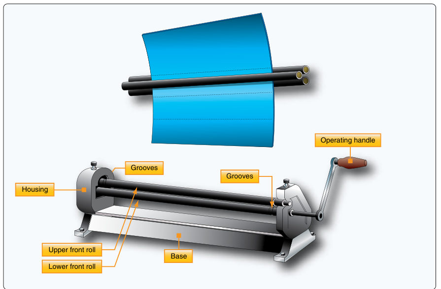
Parts and what to set
Where to buy| Part | What it does | How you set it |
|---|---|---|
| Two front (feed) rolls | Grip the sheet and carry it to the rear roll; driven by gears from the handle | Lower front roll raised or lowered to the sheet thickness with the adjusting screws, before the sheet goes in |
| Rear roll | Gives the sheet its curvature | Raise or lower by trial and error; no gauge gives a diameter |
| Upper roll release | Lets you slide the finished cylinder off the end without distortion | Release one end of the top roll |
| Grooves | Allow forming of parts with wired edges | Check clearance so a folded edge is not flattened |
H-31 = FAA-H-8083-31B, Airframe Handbook, Chapter 4, pp. 4-22 to 4-23.
Roll a curve
| Step | Action | What to do |
|---|---|---|
| 1 | Set the front rolls | Adjust the lower front roll to the metal thickness. If the part has a folded edge, leave enough clearance so the fold is not flattened. |
| 2 | Clean the rolls | For aluminum, the rolls must be clean and free of imperfections. |
| 3 | Set the rear roll | Start with a trial setting. There are no marks for a specific diameter. |
| 4 | Feed from the front | Insert the sheet between the rolls from the front. Turn the handle clockwise to start it. |
| 5 | Form a starting edge | Hold the handle firmly with the right hand and lift the metal with the left hand. If the part's edge is to be flat or nearly flat, do not form a starting edge. |
| 6 | Keep clear | Fingers and loose clothing clear of the rolls. When the metal is partly through, move the left hand to the upper edge and roll the rest. |
| 7 | Check the radius | Use a circle board or a radius gauge made to the finished radius. |
| 8 | Adjust and repeat | Run the sheet back (handle counter-clockwise), raise or lower the rear roll, and roll again. Some metal needs several passes at progressive settings. |
| 9 | Release | Release the upper roll and take the part off. |
Tapered and wired parts
Taper. Set the rear roll so the rolls are closer together at one end than at the other. The amount is found by experiment (p. 4-23).
Wired edge. Set the distance between upper and lower rolls and between the lower front roll and the rear roll slightly greater at the wired end (p. 4-23).
Typical mistakes
| Mistake | What happens | Fix |
|---|---|---|
| Trying to get the whole radius in one pass | Wrong curve, or damage | Use progressive settings and several passes |
| Dirty or damaged rolls | Marks on aluminum | Clean and inspect the rolls first |
| Folded edge pinched | Fold flattened | Leave enough clearance between the rolls |
| Hands near the rolls | Injury | Fingers and loose clothing clear |
| Forming a starting edge on a flat-edged part | Unwanted bend at the edge | Skip the starting edge if the edge is to stay flat |
Care
Keep rolls clean and free of nicks. For gear lubrication and adjustment, follow the machine maker's manual; the Handbook does not give a schedule.
Questions people actually ask
How do I know where to set the rear roll?
You do not: the Handbook says there are no gauges that indicate settings for a specific diameter, so trial and error is used (p. 4-23). Roll, check against a template, adjust, roll again.
How do I remove a closed cylinder?
On most machines the top roll can be released at one end, so the formed sheet can be taken off the machine without distortion (p. 4-22).
Limits of this guide
What the sources support, and no further.
- Not approved data. Curved structural parts follow the drawing or SRM for radius, material condition and springback.
- Capacity. The Handbook gives no thickness or width limits for slip rolls; use the maker's rating.
Where to buy
Distributors coming soon.
Sources
- FAA-H-8083-31B, AMT Handbook: Airframe (2023), Chapter 4 — pp. 4-22 to 4-23, "Slip Roll Former"; Fig. 4-60.