What the cutter leaves
Where to buy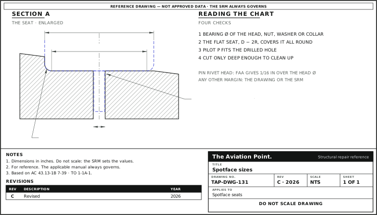
Bearing diameter to cover, by fastener
The flat seat must cover the bearing diameter all round, and the pilot fits the drilled hole, not the fastener's nominal size. The cutter column gives the smallest AT403 whose flat seat (D − 2R, R = 1/32 in) covers the bearing diameter plus the pilot gap (hole − P), so the seat still covers it with the pilot off centre. It is arithmetic on the maker's list, not a published requirement.
The AT403 is a bayonet back spotface cutter: it cuts the face away from the drill and needs access to both sides. The D − 2R rule applies to any piloted cutter. For a seat on the near face, use a front piloted counterbore with a pilot made to the hole, sized the same way with its own R.
| Fastener | Size | Hole Ø, in | Bearing Ø max, in (mm) | Smallest AT403 back cutter · D × P · flat, in | Margin, in |
|---|---|---|---|---|---|
| MS20470 universal head | 1/16 in | — | 0.131 (3.33) | — (no pilot this small in the AT403 list) | — |
| MS20470 universal head | 3/32 in | #40 · 0.098 | 0.196 (4.98) | — (no AT403 on a 3/32 in pilot covers it) | — |
| MS20470 universal head | 1/8 in | #30 · 0.1285 | 0.262 (6.65) | AT403-3 · 3/8 × 1/8 · flat 0.312 * | 0.047 |
| MS20470 universal head | 5/32 in | #21 · 0.159 | 0.328 (8.33) | AT403-4 · 7/16 × 5/32 · flat 0.375 * | 0.044 |
| MS20470 universal head | 3/16 in | #11 · 0.191 | 0.394 (10.01) | AT403-5 · 1/2 × 3/16 · flat 0.438 * | 0.040 |
| MS20470 universal head | 7/32 in | — | 0.459 (11.66) | — (hole not on our rivet drill chart) | — |
| MS20470 universal head | 1/4 in | F · 0.257 | 0.525 (13.33) | AT403-7 · 5/8 × 1/4 · flat 0.562 * | 0.030 † → AT403-8 |
| MS20470 universal head | 5/16 in | — | 0.656 (16.66) | — (hole not on our rivet drill chart) | — |
| MS20470 universal head | 3/8 in | — | 0.787 (19.99) | — (hole not on our rivet drill chart) | — |
| HL18 shear head | 5/32 in | ≈ 0.1635 | 0.262 (6.65) | AT403-3B · 3/8 × 5/32 · flat 0.312 * | 0.043 |
| HL18 shear head | 3/16 in | ≈ 0.1895 | 0.315 (8.00) | AT403-4B · 7/16 × 3/16 · flat 0.375 * | 0.058 |
| HL18 shear head | 1/4 in | ≈ 0.2495 | 0.412 (10.46) | AT403-5B · 1/2 × 1/4 · flat 0.438 | 0.026 † → AT403-6B |
| HL20 tension head | 5/32 in | ≈ 0.1635 | 0.322 (8.18) | AT403-4 · 7/16 × 5/32 · flat 0.375 * | 0.046 |
| HL20 tension head | 3/16 in | ≈ 0.1895 | 0.377 (9.58) | AT403-5 · 1/2 × 3/16 · flat 0.438 * | 0.058 |
| HL20 tension head | 1/4 in | ≈ 0.2495 | 0.440 (11.18) | AT403-6B · 9/16 × 1/4 · flat 0.500 | 0.060 |
| HL70 collar | 5/32 in | ≈ 0.1635 | 0.292 (7.42) | AT403-3B · 3/8 × 5/32 · flat 0.312 * | 0.013 † → AT403-4 |
| HL70 collar | 3/16 in | ≈ 0.1895 | 0.307 (7.80) | AT403-3C · 3/8 × 3/16 · flat 0.312 * | 0.004 † → AT403-4B |
| HL70 collar | 1/4 in | ≈ 0.2495 | 0.412 (10.46) | AT403-5B · 1/2 × 1/4 · flat 0.438 | 0.026 † → AT403-6B |
| HL70 collar | 5/16 in | ≈ 0.3125 | 0.518 (13.16) | AT403-7B · 5/8 × 5/16 · flat 0.562 | 0.044 |
| HL86 collar | 5/32 in | ≈ 0.1635 | 0.287 (7.29) | AT403-3B · 3/8 × 5/32 · flat 0.312 * | 0.018 † → AT403-4 |
| HL86 collar | 3/16 in | ≈ 0.1895 | 0.307 (7.80) | AT403-3C · 3/8 × 3/16 · flat 0.312 * | 0.004 † → AT403-4B |
| HL86 collar | 1/4 in | ≈ 0.2495 | 0.412 (10.46) | AT403-5B · 1/2 × 1/4 · flat 0.438 | 0.026 † → AT403-6B |
| HL86 collar | 5/16 in | ≈ 0.3125 | 0.518 (13.16) | AT403-7B · 5/8 × 5/16 · flat 0.562 | 0.044 |
| HL75 self-aligning collar | 5/32 in | ≈ 0.1635 | 0.365 (9.27) | AT403-4 · 7/16 × 5/32 · flat 0.375 * | 0.003 † none larger on this pilot |
| HL75 self-aligning collar | 3/16 in | ≈ 0.1895 | 0.365 (9.27) | AT403-4B · 7/16 × 3/16 · flat 0.375 * | 0.008 † → AT403-5 |
| HL75 self-aligning collar | 1/4 in | ≈ 0.2495 | 0.475 (12.06) | AT403-6B · 9/16 × 1/4 · flat 0.500 | 0.025 † → AT403-7 |
| HL75 self-aligning collar | 5/16 in | ≈ 0.3125 | 0.620 (15.75) | AT403-8B · 3/4 × 5/16 · flat 0.688 | 0.068 |
| AN3 hex head | 3/16 in | 0.190 | 0.377 (9.58) | AT403-5 · 1/2 × 3/16 · flat 0.438 * | 0.058 |
| AN4 hex head | 1/4 in | F · 0.257 | 0.440 (11.18) | AT403-6B · 9/16 × 1/4 · flat 0.500 * | 0.053 |
| AN5 hex head | 5/16 in | O · 0.316 | 0.502 (12.75) | AT403-7B · 5/8 × 5/16 · flat 0.562 * | 0.057 |
| AN6 hex head | 3/8 in | V · 0.377 | 0.565 (14.35) | AT403-9 · 7/8 × 3/8 · flat 0.812 * | 0.246 |
| AN7 hex head | 7/16 in | — | 0.627 (15.93) | — (no 7/16 in pilot in the AT403 list) | — |
| AN8 hex head | 1/2 in | — | 0.752 (19.10) | — (no 1/2 in pilot in the AT403 list) | — |
| MS21042 nut, no washer | #2 | 0.086 | 0.167 (4.24) | — (no pilot this small in the AT403 list) | — |
| MS21042 nut, no washer | #4 | 0.112 | 0.206 (5.23) | — (no 0.112 in pilot in the AT403 list) | — |
| MS21042 nut, no washer | #6 | 0.138 | 0.244 (6.20) | AT403-3 · 3/8 × 1/8 · flat 0.312 * | 0.055 |
| MS21042 nut, no washer | #8 | 0.164 | 0.290 (7.37) | AT403-3B · 3/8 × 5/32 · flat 0.312 * | 0.015 † → AT403-4 |
| MS21042 nut, no washer | #10 | 0.190 | 0.330 (8.38) | AT403-4B · 7/16 × 3/16 · flat 0.375 * | 0.042 |
| MS21042 nut, no washer | 1/4 in | F · 0.257 | 0.420 (10.67) | AT403-5B · 1/2 × 1/4 · flat 0.438 * | 0.011 † → AT403-6B |
| MS21042 nut, no washer | 5/16 in | O · 0.316 | 0.520 (13.21) | AT403-7B · 5/8 × 5/16 · flat 0.562 * | 0.039 |
| MS21042 nut, no washer | 3/8 in | V · 0.377 | 0.620 (15.75) | AT403-9 · 7/8 × 3/8 · flat 0.812 * | 0.191 |
Bearing diameters from the data sheets linked in the first column (MS20470: head diameter plus tolerance; Hi-Lok: A max; AN bolts: across flats, max; MS21042: bearing ring diameter, max). Holes: rivets, the final drill on the rivet drill chart; Hi-Lok, ≈ the pin shank D max (the drawing gives the hole); AN bolts and MS21042 1/4 in and up, the first letter drill above the bolt (AC 43.13-1B par. 7-39, as on drills); AN3 and numbered sizes, nominal. Cutters: ATS AT403 list, fraction pilots only. * No pilot of the hole's size in the list: the nearest one under it is shown, never more than 1/64 in under. A loose pilot lets the cutter sit off centre by half the gap and tilt; use a pilot made to the hole where you can. † The smallest covering cutter leaves no allowance for pilot clearance or hole position. With less than about 1/32 in of margin (flat seat − bearing Ø − pilot gap; half the FAA's 1/16 in pin rivet allowance, applied by analogy), take the next size up, after the arrow. ‡ HL75 is a self-aligning collar assembly: like AN950/AN955 washers it takes up some angle, but its angle capacity is not published. Hex heads: in a seat with a wall on the high side, also clear the across-corners (about 1.15 × across flats on a sharp hexagon) and the socket.
Bayonet back spotface cutters, AT403 list
The maker lists each cutter by diameter D and pilot P as a bayonet spotface cutter on the AT404 back cutter pilot: the pilot goes through the hole, the cutter fits on it on the far side and cuts back toward the drill, so both sides must be reachable. HSS, four flutes, corner radius 1/32 in. The flat seat column is D − 2R, here D − 1/16 in.
| Part number | D, in | Pilot P, in | Flat seat, in |
|---|---|---|---|
| AT403-1 | 1/4 | 3/32 | 0.1875 |
| AT403-1B | 1/4 | 1/8 | 0.1875 |
| AT403-2 | 5/16 | 1/8 | 0.2500 |
| AT403-2B | 5/16 | 5/32 | 0.2500 |
| AT403-3 | 3/8 | 1/8 | 0.3125 |
| AT403-3B | 3/8 | 5/32 | 0.3125 |
| AT403-3C | 3/8 | 3/16 | 0.3125 |
| AT403-4 | 7/16 | 5/32 | 0.3750 |
| AT403-4B | 7/16 | 3/16 | 0.3750 |
| AT403-5 | 1/2 | 3/16 | 0.4375 |
| AT403-5B | 1/2 | 1/4 | 0.4375 |
| AT403-6 | 9/16 | 3/16 | 0.5000 |
| AT403-6B | 9/16 | 1/4 | 0.5000 |
| AT403-7 | 5/8 | 1/4 | 0.5625 |
| AT403-7B | 5/8 | 5/16 | 0.5625 |
| AT403-8 | 3/4 | 1/4 | 0.6875 |
| AT403-8B | 3/4 | 5/16 | 0.6875 |
| AT403-9 | 7/8 | 3/8 | 0.8125 |
| AT403-10 | 1 | 3/8 | 0.9375 |
Source: ATS, AT403 page (read 07-11-2026): “Bayonet Spotface Cutter”, a drawing marked “back spotface”, “Requires AT404 series pilot”; AT404 is the “Back Cutter Pilot”. For the near face, other makers list front piloted aircraft counterbores with interchangeable pilots and a 1/4 in shank, for example 27/32 in with a 3/16 in pilot hole (Brown, BAT4015-9E).
Rules from the public sources
| Item | Rule | Source |
|---|---|---|
| Pin rivet head | Spotface when needed so the head fits tightly; spotface 1/16 in larger in diameter than the head | FAA-H-8083-31B p. 4-49 |
| Bolt head and nut | Holes flush to the surface and clean, to give full bearing for the head and the nut | AC 43.13-1B par. 7-39 |
| Squareness | Hole perpendicular to the surface the head seats on, within ±3°, unless the drawing says otherwise | TO 1-1A-1 par. C.8.1 |
| Angled bolt | Ball socket and seat washers AN950 and AN955, used together as a pair | AC 43.13-1B par. 7-88 |
| Head-to-shank radius | Countersunk washer NAS143C or MS20002C seats the radius; plain washer under the nut | AC 43.13-1B p. 7-15 |
| Hi-Lok collar | Has its own internal counterbore for grip variation: a feature of the collar, not a spotface in the part | FAA-H-8083-31B p. 4-50 |
| Depth | No general public limit: the drawing, the SRM or engineering | — |
| Speed | Maximum for countersinking and counterboring: 500 rpm aluminium, 150 rpm titanium and steel | TO 1-1A-1 Table C-4 |
| Bare metal | Bare aluminium recoated at once; holes treated and primed before installation, as AC 43.13-1B asks for doubler rivet holes (applied by analogy) | TO 1-1A-1 2.4; AC 43.13-1B 6-132 |
How to do the work: Spotfacing: seating heads and tails flat.
Worked example — HL20 tension head, 1/4 in
A 1/4 in HL20 Hi-Lok passes through a fitting, and its head lands on the radius of the far face. The drawing allows a spotface there and gives no diameter. The far face can be reached by hand but not with the drill, so the seat is cut with a bayonet back spotface cutter: the pilot goes through the hole from the drill side, and the cutter, fitted on the far side, cuts back toward the drill.
- Bearing diameter from the data sheet: 0.440 in (A max).
- Hole ≈ the pin shank, 0.2495 in max: the 1/4 in pilot fits it, so there is no pilot gap.
- The flat seat must cover it: D − 2R ≥ 0.440 in. R is 1/32 in on the AT403, so D ≥ 0.5025 in.
- AT403-5B (1/2 × 1/4) leaves a flat of 0.4375 in: short. AT403-6B (9/16 × 1/4) leaves 0.500 in, a margin of 0.060 in: it covers the head.
- Cut only until the seat is flat all round, then check the head seats tight.
Questions people actually ask
Is there a standard spotface diameter for a bolt or a nut?
No public figure. AC 43.13-1B par. 7-39 asks for full bearing for the head and the nut; the size and any margin come from the drawing or the SRM.
Why is the flat seat smaller than the cutter?
The cutter's corners are radiused, 1/32 in on the AT403, so the outer ring of the cut is a fillet, not flat. The flat seat is D minus twice the radius.
What about the rivet's shop head on the far side?
Its diameter limits are in FAA-H-8083-31B Fig. 4-76, rivet formed head dimensions. Size the far-side seat from the maximum there, and check the head with the shop head calculator.
Limits — when NOT to use this chart
What the sources support, and no further.
- The drawing or the SRM governs the spotface diameter, depth and remaining thickness.
- One published margin. The 1/16 in over the head is printed for pin rivet heads only.
- Washers and shop heads are not listed. Under a washer, cover its outside diameter from its data sheet; shop heads, FAA Fig. 4-76.
- Wrench clearance is not checked. A hex head or nut in a seat with a wall must clear its across-corners, and the socket must fit inside the spotface.
- What P means. The maker lists a P with each cutter and sells AT404 pilots by diameter; reading P as the diameter of the pilot that rides in the hole is ours, not stated on the page.
- No Hi-Shear pin rivet rows. There is no Hi-Shear data sheet on this site; for them the FAA gives 1/16 in over the head (FAA-H-8083-31B p. 4-49).
- Hole sizes come from the site's drill charts and data sheets; the drawing's hole tolerance governs the pilot.
Where to buy
Distributors coming soon.
Keep going
Calculators
Guides
How to do it
Data sheets
Books

Buy
Distributors coming soon.
Sources
- FAA-H-8083-31B, Aviation Maintenance Technician Handbook: Airframe, Chapter 4 — p. 4-49, spotface under the pin rivet head, 1/16 in over the head; p. 4-50, inspection and the Hi-Lok collar counterbore; Fig. 4-76, formed head dimensions.
- FAA AC 43.13-1B CHG 1, Chapter 7 — Par. 7-39, full bearing for head and nut; par. 7-88, AN950 and AN955 washers; p. 7-15, NAS143C and MS20002C; par. 6-132, holes treated and primed.
- TO 1-1A-1 / NAVAIR 01-1A-1, General Manual for Structural Repair (Distribution A) — Par. C.8.1, hole perpendicular to the seat within ±3°; Table C-4, maximum countersinking and counterboring speeds; sec. 2.4, recoat bare aluminium.
- ATS, AT403 bayonet spotface cutter and AT404 back cutter pilot — Diameter and pilot of the 19 cutters, HSS, four flutes, 1/32 in corner radius, drawing marked back spotface; AT404 back cutter pilots.
- Wikipedia, Spotface (secondary) — Back spotfacing: the tool reaches the far side and cuts back toward the spindle; the pilot locates the cutter on the hole.
- Fastener data sheets on this site — MS20470, HL18, HL20, HL70, HL86, HL75, AN3 to AN8 and MS21042: the bearing diameters in the first table. Holes: the rivet drill chart and the drills page.