The hole in four steps, the fit, and the oversize ladder
Where to buy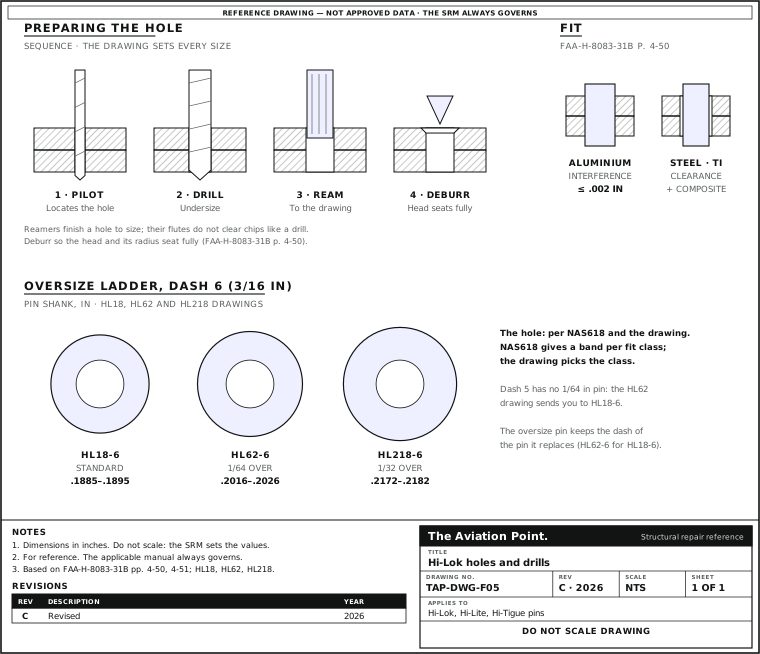
Fit by material
| Structure or pin | Fit | Source |
|---|---|---|
| Aluminium structure | Interference; the hole is prepared so that it does not exceed 0.002 in | FAA-H-8083-31B p. 4-50 |
| Steel, titanium | Clearance | FAA-H-8083-31B p. 4-50 |
| Composite | Clearance | FAA-H-8083-31B p. 4-50 |
| Hi-Tigue pin | Controlled interference: the bead cold-works the hole | FAA-H-8083-31B p. 4-50; T.O. 1-1A-1 par. 5.3.1.1.8 |
The limit keeps the internal stresses next to the hole down (FAA-H-8083-31B p. 4-50). The hole bands are in NAS618 (table below); the drawing picks the class.
The pins and their oversizes
| Standard pin | Head, material | 1/64 in oversize | 1/32 in oversize |
|---|---|---|---|
| HL18 | Protruding shear head, alloy steel | HL62 | HL218 |
| HL19 | 100° flush shear head, alloy steel | HL63 | HL219 |
| HL10 | Protruding shear head, titanium | HL110 | No public number |
| HL11 | 100° flush shear head, titanium | HL111 | No public number |
Pairs as the data sheets title them (HL62 and HL218 for HL18, HL63 and HL219 for HL19, HL110 for HL10, HL111 for HL11). The oversize series also holds HL64, HL65, HL220 and HL221: check each data sheet for the pin it replaces. Use part numbers to identify these fasteners; they are easily confused (FAA-H-8083-31B p. 4-50).
Pin diameters, standard and oversize
| Dash | Nominal | HL18, standard | HL62, 1/64 in over | HL218, 1/32 in over |
|---|---|---|---|---|
| -5 | 5/32 in | .1625–.1635 | None: use HL18-6 | None: use HL62-6 |
| -6 | 3/16 in | .1885–.1895 | .2016–.2026 (13/64) | .2172–.2182 (7/32) |
| -8 | 1/4 in | .2485–.2495 | .2641–.2651 (17/64) | .2797–.2807 (9/32) |
| -10 and up | 5/16 to 1 in | On the HL18 drawing | On the HL62 drawing | On the HL218 drawing |
Pin shank D, in inches, from the Hi-Shear drawings HL18, HL62 (rev. 18) and HL218; the HL62 drawing covers -6 to -32. The oversize pin keeps the dash of the pin it replaces. Titanium pins (HL10, HST10AG) have slightly different shank limits: see their data sheets.
NAS618 hole limits for the standard pins
| Dash | Pin shank D, in | Column A hole, minimum clearance | Column G hole, transition | Column F hole, interference |
|---|---|---|---|---|
| -5 (5/32 in) | 0.1625–0.1635 | 0.1635–0.1645 | 0.161–0.164 | 0.159–0.161 |
| -6 (3/16 in) | 0.1885–0.1895 | 0.1895–0.1905 | 0.187–0.19 | 0.185–0.187 |
| -8 (1/4 in) | 0.2485–0.2495 | 0.2495–0.2505 | 0.247–0.25 | 0.245–0.248 |
| -10 (5/16 in) | 0.311–0.312 | 0.312–0.313 | 0.309–0.313 | 0.307–0.31 |
| -12 (3/8 in) | 0.3735–0.3745 | 0.3745–0.3755 | 0.371–0.375 | 0.369–0.372 |
| -14 (7/16 in) | 0.436–0.437 | 0.437–0.438 | 0.434–0.438 | 0.432–0.435 |
| -16 (1/2 in) | 0.4985–0.4995 | 0.4995–0.5005 | 0.496–0.5 | 0.494–0.497 |
Steel, titanium and composite take a clearance fit, column A (FAA-H-8083-31B p. 4-50; Hi-Shear 2-1520 p. 7). In aluminium the fit is interference, capped at 0.002 in by FAA-H-8083-31B p. 4-50 and at 0.0015 in by the Hi-Shear instructions; at the worst case columns G and F go past that cap, so the drawing or the SRM sets the interference hole. NAS618 sheets 3, 4, 6 and 7 (AIA, 1986, reaffirmed 1992); pin D also on Hi-Shear drawings HL19 rev. 29, HL63 and HL219.
NAS618 hole limits for the oversize pins
| Dash | 1/64 in oversize pin D | Column J hole | 1/32 in oversize pin D | Column R hole |
|---|---|---|---|---|
| -5 | None: use the -6 standard pin | — | None: use the 1/64 oversize -6 | — |
| -6 | 0.2016–0.2026 | 0.2026–0.2036 | 0.2172–0.2182 | 0.2182–0.2192 |
| -8 | 0.2641–0.2651 | 0.2651–0.2661 | 0.2797–0.2807 | 0.2807–0.2817 |
| -10 | 0.3266–0.3276 | 0.3276–0.3286 | 0.3422–0.3432 | 0.3432–0.3442 |
| -12 | 0.3891–0.3901 | 0.3901–0.3911 | 0.4047–0.4057 | 0.4057–0.4067 |
| -14 | 0.4516–0.4526 | 0.4526–0.4536 | 0.4672–0.4682 | 0.4682–0.4692 |
| -16 | 0.5141–0.5151 | 0.5151–0.5161 | 0.5297–0.5307 | 0.5307–0.5317 |
J and R are the precision minimum-clearance columns for the oversize shanks; bands of 0.001 in are finished with a reamer. NAS618 sheets 3, 4, 6 and 7 (AIA, 1986, reaffirmed 1992); pin D also on Hi-Shear drawings HL19 rev. 29, HL63 and HL219.
The hole: NAS618 and the drawing
The maker's drawing sends the hole preparation to NAS618 (HL62 drawing, note 4). NAS618 gives the hole band for each pin diameter and fit class (table above): column A is the minimum clearance, G the transition and F the interference fit. The aircraft drawing, the SRM or the approved repair data says which class applies.
TM 1-1500-204-23-6 Table 2-6 (Huck and Hi-Lok bolt substitution) does print hole sizes. Against the HL18 pin diameter they give 0.0045 to 0.0075 in of interference, more than the 0.002 in limit of FAA-H-8083-31B. The two sources disagree, so this guide uses neither figure as a shop size.
The Hi-Lok calculator picks the pin and collar by grip; fastener hole drill and drill for a part number cover the drills of the other fasteners.
Drilling and reaming, in order
| Step | What | Why, and the source |
|---|---|---|
| 1 · Pilot | A small drill locates the hole | See drilling |
| 2 · Drill undersize | Leave stock for the reamer | Reamer flutes are not designed to remove chips like a drill (FAA-H-8083-31B, Reamers) |
| 3 · Ream | To the size on the drawing or NAS618 | Reamers enlarge holes and finish them smooth to size (FAA-H-8083-31B) |
| 4 · Deburr | Break the edge so the head seats fully | The pin has a slight radius under its head (FAA-H-8083-31B p. 4-50) |
| 5 · Check | The hole against the drawing's limits, before the pin goes in | The drawing or NAS618 |
The order and the reasons, not the sizes: those are the SRM's. Close-tolerance bolts follow the same logic: their shanks permit a very close fit with reamers (TM 1-1500-204-23-6 par. 2-2g).
Hi-Lok, Hi-Lite and Hi-Tigue
| Hi-Lok | Hi-Lite | Hi-Tigue | |
|---|---|---|---|
| What it is | Threaded pin and self-locking collar; the collar wrenching part shears off at a set torque | Like Hi-Lok, shorter transition, about one thread less; all titanium | Hi-Lok with a bead that cold-works the hole in an interference fit |
| Pins in the data sheets | HL18, HL19 (alloy steel); HL10, HL11 (titanium) | HST10AG, HST11AG | HLT900, HLT912 |
| Collars | Aluminium alloy, CRES or alloy steel | Not interchangeable with Hi-Lok collars | Pin and collar assembly |
| Interchange | Can replace a Hi-Lite in most applications | Cannot replace a Hi-Lok | To the drawing |
FAA-H-8083-31B pp. 4-50, 4-51; T.O. 1-1A-1 pars. 5.3.1.1.7 and 5.3.1.1.8. The hole for each is prepared to the drawing, as for Hi-Lok.
After installation
| Check | Good | Source |
|---|---|---|
| Collar | Wrenching part sheared off; the remaining collar carries the preload without a torque check | FAA-H-8083-31B p. 4-50 |
| Head | Seated fully on the surface | FAA-H-8083-31B p. 4-50 |
| Pin protrusion and defects | Within the limits of the installation data | Hi-Lok installation |
Questions people actually ask
What drill do I use for a 3/16 in Hi-Lok?
The HL18-6 pin is .1885 to .1895 in. NAS618 column A, the clearance hole for steel, titanium and composite, is .1895 to .1905 in: pilot, drill undersize (#17) and ream. In aluminium the fit is interference, not over 0.002 in (FAA-H-8083-31B p. 4-50), and the drawing sets that hole.
The hole is oversize. What next?
If the SRM or the engineering data allows it: a 1/64 in oversize pin (HL62 for HL18, HL63 for HL19, HL110 or HL111 for titanium), then a 1/32 in one (HL218, HL219), each in a hole prepared for it. Dash 5 has no 1/64 in pin: the HL62 drawing sends you to HL18-6.
Can a Hi-Lok go into composite with interference?
FAA-H-8083-31B p. 4-50 gives a clearance fit for steel, titanium and composite; interference is for aluminium structure.
Hi-Lite or Hi-Lok?
A Hi-Lite can be replaced by a Hi-Lok in most applications; a Hi-Lok cannot be replaced by a Hi-Lite. Their collars are not interchangeable (FAA-H-8083-31B p. 4-51).
Limits of this guide
What the sources support, and no further.
- Hole bands, not a shop size for aluminium. NAS618 columns G and F go past the interference cap at the worst case, and TM Table 2-6 disagrees with the FAA limit, so the drawing sets the aluminium hole.
- Pin diameters beyond -8 are on the maker's drawings; HL63 to HL65, HL110 and HL111 were not re-read for this guide.
- Composite: only the FAA clearance rule is given; drilling methods for composite belong to the repair data.
- Reference data, not approved data. The SRM, the drawing or the approved repair data governs over every figure here.
Where to buy
Distributors coming soon.
Keep going
Calculators
Guides
How to do it
Data sheets
Books
Buy
Distributors coming soon.
Sources
- FAA-H-8083-31B, Aviation Maintenance Technician Handbook, Airframe, chapter 4 — Pp. 4-50, 4-51: Hi-Lok, Hi-Tigue and Hi-Lite, fit and the 0.002 in limit; Reamers.
- Hi-Shear (LISI Aerospace) drawings HL18, HL62 rev. 18 and HL218 — Pin shank diameters, the dash 5 note and the NAS618 hole note.
- TM 1-1500-204-23-6 — Par. 2-2g close-tolerance bolts; Table 2-6, Huck and Hi-Lok bolt substitution (not used as a shop size).
- T.O. 1-1A-1 (NAVAIR 01-1A-1) — Pars. 5.3.1.1.7 Hi-Lok and 5.3.1.1.8 Hi-Tigue.
- NAS618, Fastener: recommended shank, hole and head-to-shank fillet radius limits (AIA) — Sheets 3, 4, 6 and 7: shank and hole columns A to G, J and R. 1986 sheets, reaffirmed 1992; the 2010 edition may revise a figure.