What a bond is for
Where to buyA bond is a joint that has to carry current on purpose. It has three jobs: to give lightning a low-resistance, low-impedance path so the structure is not torn, arced or set on fire; to keep electromagnetic interference down; and to remove the risk of a spark from static charge or a fault current.
Paint, primer and anodic film are insulators, so a bonded joint starts with a prepared surface. The same hardware you rivet or bolt with makes the bond, so the work is done while the structure is assembled. A bond is also never judged by eye: it is measured. The numbers in this guide are production practice for how much to prepare, and public limits for how good the result must be.
What makes a bond
| Means | Where it is used |
|---|---|
| Rivets, screws, bolts, clamps | The ordinary joint of the structure, once its faying surfaces are bare |
| Braids and bonding straps | Across hinges, shock mounts and movable parts (jumpers) |
| Conductive paste or adhesive | Where two parts touch and there is no fastener to carry the current |
| Conductive paint | Conductive coatings on composite skins |
| Conductive gaskets | Between faces that must seal and conduct |
How much finish to strip
| Case | What is stripped | Size, inch first |
|---|---|---|
| Plain head | Screw or bolt, head not countersunk: a circle of head diameter + 2 mm | Head Ø + 0.079 in (2 mm) |
| With a washer | The same screw or bolt: a circle of washer diameter + 2 mm | Washer Ø + 0.079 in (2 mm) |
| Drawn area | The contact area on the drawing is 2 mm larger than the real contact surface, so the margin is already in it | 0.079 in (2 mm) |
| Countersunk screw | Only the nut side. The countersink stays as it is | — |
| Solid rivets | In primed, painted or anodised parts only the holes, the countersinks and the dimples are left bare. No surface stripping | — |
| Bulbed blind | Bulbed blind rivets: the bearing faces of the head and of the bulb, to head or bulb Ø + 2 mm | Ø + 0.079 in (2 mm) |
| Countersunk blind | Blind rivets and bolts: the countersink left bare; the bulb side stripped to bulb Ø + 2 mm | Ø + 0.079 in (2 mm) |
Millimetres are printed with their unit in the production practice; the inch value is our conversion (2 mm = 0.079 in). These are practice values, not limits: the drawing or the SRM sets the dimension. Abrasive grade 320 or finer. Use the right pilot size on the brush or the hole goes oval, and do not press hard or the part is spot-faced.
What you strip and what you leave
Strip: primer, paint and anodic films. Do not strip, only degrease: zinc, tin, cadmium and chemical conversion coatings (Alodine type). They conduct well enough and stripping them removes their corrosion protection. Chromium plating is on some lists and not on others, so treat it as unconfirmed and follow the drawing.
On aluminium the bare metal is treated again: apply a conductive chemical treatment within 24 hours of removing the finish (AC 43.13-1B 11-189). The Alodine and MIL-DTL-5541 guide and the metallic coatings guide say which coatings these are. A final degrease with the solvent the SRM approves goes before paste or adhesive.
Paste, adhesive and gaskets
Where parts touch with no fastener in the path, put a conductive paste, adhesive, sealant or gasket between the bare faces. A conductive adhesive has a short working life: assemble the parts within 15 minutes of applying it. A paste or adhesive is a product from the SRM's approved list, not a choice made at the bench.
See the sealing guide for the sealants that go over a finished bond.
Protecting the finished bond
After assembly, coat the whole assembly and the stripped zones, and carry the coat 0.16 to 0.20 in (4 to 5 mm) past each side of the stripped area. The varnish covers the bond with at least 0.20 in (5 mm) round the element. In interior and hot zones the cover is a protection varnish; on the exterior it is a polysulphide sealant, which is also allowed on the interior side of a through-bulkhead bond.
Refinish promptly: AC 43.13-1B 11-189 asks for the finish to be restored within 24 hours of the surface being cleaned. Painting over an area meant for bonding is a common cause of electromagnetic problems.
A bonded joint, in order
| Step | Action | What to do |
|---|---|---|
| 1 | Strip | Remove primer, paint and anodic film in the circle the case asks for, with abrasive grade 320 or finer. Leave zinc, tin, cadmium and conversion coat. |
| 2 | Treat | On aluminium, restore the conductive chemical film within 24 hours. Degrease with the approved solvent. |
| 3 | Add the path | Paste, adhesive, sealant or gasket between bare faces that touch. Assemble an adhesive within 15 minutes. |
| 4 | Fasten | Install the fastener. Do not use self-tapping screws for a bond. |
| 5 | Measure | Measure after the mechanical joint is complete, with a bonding tester or a millivolt-drop test. Record the value. |
| 6 | Protect | Seal and refinish within 24 hours, past the stripped zone by 0.16 to 0.20 in (4 to 5 mm). |
Six bonding cases, simplified
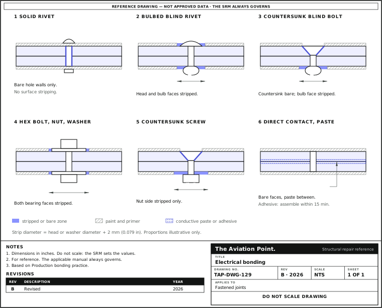
Bonding cases by fastener type
| Case | Where the current goes | What is prepared |
|---|---|---|
| Solid rivet | Protruding or countersunk: the shank in a bare hole, plus the countersink | Holes, countersinks and dimples bare; the surface is not stripped on primed, painted or anodised parts |
| Bulbed blind rivet | Protruding or low head: the head and the bulb bearing faces | Strip both faces to head or bulb Ø + 2 mm |
| Countersunk blind, metal | Rivet or bolt: the countersink and the bulb side | Countersink bare; strip the bulb side to Ø + 2 mm |
| Countersunk blind, composite | Skin with surface mesh: the mesh at the countersink, and the collar or bulb side | The mesh, not the resin, carries the current: what is exposed follows the repair data |
| Hex bolt, nut, washer | Under the washer or head, and the nut face | Strip a circle of washer (or head) Ø + 2 mm on each face |
| Countersunk screw, nut | In metal, with a nut: the nut face | Strip only the nut side |
| Screw into a nutplate | The nutplate seat and the screw bearing face | The same Ø + 2 mm rule on each bearing face |
| Bolt with cable terminal | The terminal under the head or nut | Strip under the terminal; terminal hardware by the AC 43.13-1B tables |
| Stud or insert in a block | The seating face of the block | Strip the seat to the same Ø + 2 mm |
| Gasket or direct contact | Quarter-turn fastener, conductive gasket or two touching faces: the gasket or faying faces | Bare faces with paste, adhesive, sealant or a conductive gasket between |
| Copper foil and splice | A foil bridging a gap | Foil and splice make the path; the foil ends are the contact areas |
| Sandwich panels | Equipment, through-bolts and countersunk screws: a copper shim, a metallic spacer or a brass cup carries the path across the core | Per the repair drawing; the core itself does not carry current |
Bonding drawings give each of these cases its own symbol. This table names the case and the preparation; the aircraft's drawing sets the symbol and the dimension.
Bond classes and public resistance limits
| Class | Public limit | Where it is written |
|---|---|---|
| R (radio frequency, EMI) | 2.5 mΩ per joint | MIL-STD-464C 5.10.3; NASA-STD-4003A |
| L (lightning) | 2.5 mΩ per joint on the outer mould line. Jumpers of at least 12 AWG (6,530 circular mils) stranded copper or 10 AWG (10,380 circular mils) stranded aluminium; 40,000 circular mils where arcing is possible | NASA-STD-4003A 4.1.5, 5.1.2; AC 43.13-1B 11-193 |
| H (shock and fault) | 0.1 Ω (NASA-STD-4003A). Aircraft: 0.01 Ω (1/100 ohm) or less between structure and metallic conduits or equipment, enough to carry the fault current without sparking, fusing or dangerous heating | NASA-STD-4003A 4.1.3; AC 43.13-1B 11-192 |
| S (static) | 1.0 Ω; for parts over 3 in² area and 3 in in any dimension, less than 1 Ω, clean and dry | NASA-STD-4003A 4.1.6; AC 43.13-1B 11-187c |
| C (current return) | Set by voltage drop; the default is 3.5 % of the bus voltage | NASA-STD-4003A 4.1.2.1 |
| Equipment frames | Exposed conducting frames under 2.5 mΩ to structure; each jumper connection not more than 0.003 Ω | AC 43.13-1B 11-188f, 11-189 |
| Fuel systems | 1 Ω or less to structure for small metallic objects in a tank and other fuel-system parts | AC 43.13-1B, chapter 11, section 15 |
Limits only from public documents: MIL-STD-464C, NASA-STD-4003A and AC 43.13-1B. The aircraft's maintenance manual sets the limit that applies, and it can be stricter. 1 mΩ = 0.001 Ω.
Public practice that is easy to get wrong
| Where it is written | Rule |
|---|---|
| AC 43.13-1B, Change 1, Chapter 11, Section 15 (Grounding and Bonding) | Attach the bond to the basic structure, not through another bonded part. |
| AC 43.13-1B, Change 1, Chapter 11, Section 15 (Grounding and Bonding) | Do not bond with self-tapping screws: use standard threaded screws or bolts. |
| AC 43.13-1B 11-189 | Use suitable washers when bonding aluminium or copper to a dissimilar structure, so that the corrosion happens on the washer. |
| AC 43.13-1B 11-189 | Aluminium-alloy jumpers in most cases; copper jumpers for stainless steel, cadmium-plated steel, copper, brass and bronze. The part likely to corrode should be the jumper or the hardware. Avoid solder to attach jumpers. |
| AC 43.13-1B 11-189 | Jumpers as short as practicable, each connection not above 0.003 Ω, and clear of moving parts. |
| AC 43.13-1B 11-189 | Remove paint and anodic film from the attachment surface. On aluminium apply a conductive chemical treatment (Alodine type) within 24 hours of removing the finish, and refinish within 24 hours. In a salt-spray environment seal dissimilar metals with a non-corrosive sealant of the MIL-S-8802 type. |
| AC 43.13-1B 11-189 | No wiring grounded directly to magnesium. |
| AC 43.13-1B, Change 1, Chapter 11, Section 15 (Grounding and Bonding) | Heavy-current ground brackets (generators, TRUs, batteries, external power): metal-to-metal attachment with at least three fasteners in a triangular or rectangular pattern; carbon-fibre structure needs another ground path. |
| NASA-STD-4003A 5.4 | Carbon fibre can be bonded for static discharge but not for Classes C or H. Expose the graphite by removing the non-conductive epoxy, then use conductive epoxy. |
| NASA-STD-4003A 5.1; AC 43.13-1B 11-189 | Spacecraft practice excludes cadmium-plated hardware, zinc-plated hardware and anodised washers for bonding. Aircraft practice in the AC 43.13-1B tables uses cadmium-plated steel hardware: the contexts differ, so follow the aircraft's own manual. |
How to measure a bond
Measure after the mechanical connection is complete. AC 43.13-1B 11-188j asks for a high-quality low-resistance instrument (an AN/USM-21A or equivalent bonding tester) or the millivolt-drop test of its figure 11-19. A bonding tester or a milliohmmeter is such an instrument.
A hand-held multimeter is not a bonding tester. The limits are a few milliohms and a general-purpose meter does not resolve them. Record the value you measure against the limit the manual gives.
Bonding on composite structure
Carbon fibre is about 1,000 times more resistive than aluminium and epoxy about 1,000,000 times more resistive through the thickness, so a composite skin in a strike zone carries a conductive layer: nickel-coated graphite cloth, copper or aluminium mesh, aluminised glass fibre or conductive paint. Fine aluminium mesh in glass and aramid parts corrodes round bolt and screw holes and breaks the bond: the mesh is replaced and the bond is measured again.
A repair removes the finish and the conductive coating at least 1 in beyond the taper before sanding, and restores the conductive coating at the end. The lightning protection guide covers the mesh ply, hinge jumpers and the check. Carbon is cathodic against aluminium and cadmium: the galvanic corrosion check shows which part corrodes.
Questions people actually ask
Why strip the paint round a fastener for a bond?
Paint, primer and anodic film do not conduct. A fastener through painted metal holds the parts together but leaves the current to find another path. The bearing faces are stripped so the metal of the fastener touches the metal of the structure.
How big a circle do I strip round a bolt head?
Production practice strips a circle of the head diameter plus 2 mm (0.079 in) for a plain head, and the washer diameter plus 2 mm when there is a washer. A countersunk screw is stripped on the nut side only. The drawing or the SRM sets the value.
Do I strip Alodine or cadmium off before bonding?
No. Zinc, tin, cadmium and chemical conversion coatings conduct well enough and are only degreased. On bare aluminium, a conductive chemical film goes back on within 24 hours (AC 43.13-1B 11-189).
What resistance must a bond have?
It depends on the class. The public documents give 2.5 mΩ per joint for radio-frequency and lightning bonds (MIL-STD-464C, NASA-STD-4003A), 0.1 Ω for shock and fault (NASA-STD-4003A), 0.01 Ω between structure and metallic conduits or equipment on aircraft (AC 43.13-1B 11-192) and 1 Ω for static. The aircraft's manual gives the figure for your joint.
Can I check a bond with a multimeter?
No. A general-purpose multimeter does not resolve milliohms. Use a bonding tester or the millivolt-drop test that AC 43.13-1B 11-188j describes.
Can a self-tapping screw be a bond?
AC 43.13-1B says not to use self-tapping screws for bonding. Use standard threaded screws or bolts, with the faying surfaces prepared before assembly.
Limits of this guide
What the sources support, and no further.
- Strip sizes are practice, not limits. The 2 mm margin, the 4 to 5 mm coat and the 15-minute adhesive time are production values; the drawing or the SRM overrides them.
- Resistance limits are public ones. MIL-STD-464C, NASA-STD-4003A and AC 43.13-1B. The NASA standard is written for launch vehicles and spacecraft: its ban on cadmium-plated bonding hardware does not carry over to aircraft practice, which uses cadmium-plated steel in the AC tables.
- Not covered. Fuel-tank lightning protection, antennas and air-data probes (AC 43.13-1B 11-194), shielding, and the test set-up for a given instrument.
- The instrument. The public documents above ask for a low-resistance instrument or a millivolt-drop test and do not name a four-wire (Kelvin) milliohmmeter, so this guide does not specify one.
Where to buy
Distributors coming soon.
Keep going
Calculators
Guides
Books
Buy
Distributors coming soon.
Sources
- FAA AC 43.13-1B, Change 1, Chapter 11, Section 15, Grounding and Bonding — Paragraphs 11-187c (static bonds), 11-188f and 11-188j (equipment frames, instruments and the millivolt-drop test, figure 11-19), 11-189 (finish removal, jumpers, hardware), 11-192 (shock hazard), 11-193 (lightning).
- NASA-STD-4003A, Electrical Bonding for NASA Launch Vehicles, Spacecraft, Payloads and Facilities — Bond classes R, L, H, S and C (4.1), bond straps and fasteners (5.1), faying surfaces (5.2), composites (5.4) and verification (5.5). Written for space hardware; used here only for the public limits.
- MIL-STD-464C, Electromagnetic Environmental Effects Requirements for Systems — Paragraph 5.10.3, electrical bonding; Appendix A on painting over bonding areas.
- FAA-H-8083-31B, Aviation Maintenance Technician Handbook: Airframe, Chapter 7 — Conductive layers in composites, mesh corrosion round fastener holes, the finish removed beyond the repair taper.