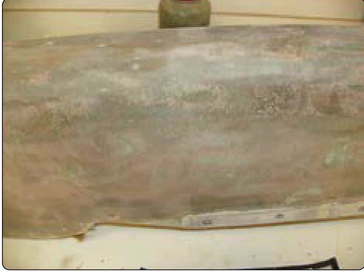
Mesh ply over a repair, resistance check and hinge jumpers
Where to buy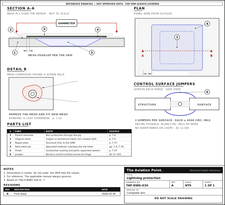
Restore the path, one step at a time
| Step | Action | What to do |
|---|---|---|
| 1 | Strip the finish | The finish comes off with the conductive coating. |
| 2 | Repair the structure | Do the normal structural repair to the SRM. |
| 3 | Rebuild the conductive layer | After the plies cure, the mesh or conductive coating goes on. Use the material the SRM names. |
| 4 | Apply the finish coat | It goes on over the conductive layer. |
| 5 | Measure | These repairs generally call for a conductivity test with an ohmmeter. The limit is the SRM's. |
Conductive layers you will meet
| Material | Where | Watch for |
|---|---|---|
| Copper mesh | Fabric or prepreg layer at the surface (handbook figure 7-8) | Approved material only |
| Aluminium mesh | Fine mesh in many fibreglass and aramid parts (figure 7-9) | Corrodes round bolt and screw holes |
| Nickel-coated graphite cloth | Surface ply, wet layup or prepreg | Same layup rules as the plies |
| Aluminized fibreglass | Surface ply | Check it is the specified type |
| Conductive paint or coating | Top finish over the laminate | Goes back after the repair |
| Bonded strips | Radomes: strips on the outside | High resistance from shorts in the strips or fittings; strips disbonding |
FAA-H-8083-31B Vol. 1 pp. 7-5, 7-6, 7-8, 7-15 and 7-40 to 7-41. All are available for wet layup and as prepreg.
Restoring the path
The repair is two jobs in one visit. First the normal structural repair, to the SRM. Then the conductive layer: recreate the electrical conductivity designed into the part, with the material the SRM names. The handbook is firm that this means approved materials from authorised vendors, including the potting compounds, sealants and adhesives, not just the mesh.
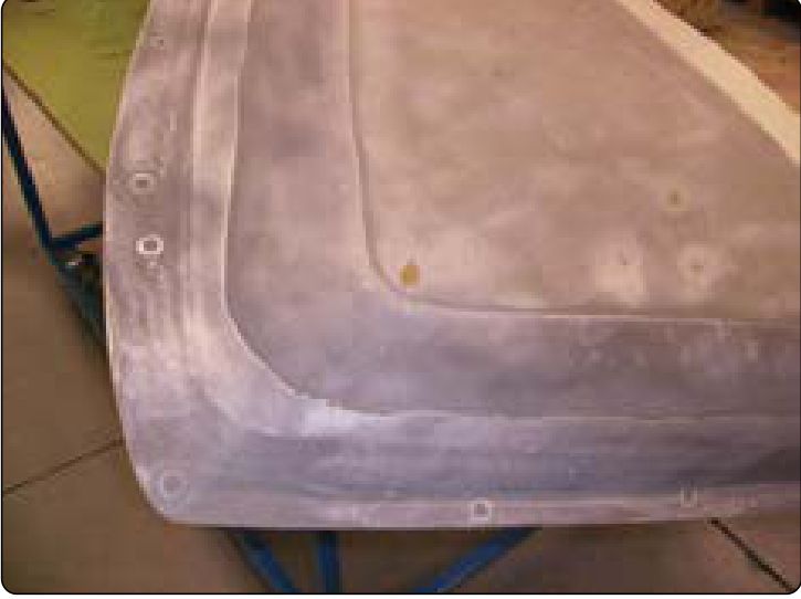
Before the repair, the finish comes off with the conductive coating: on a sandwich repair, strip the finish for at least 1 in beyond the taper border. After the plies cure, the mesh or conductive coating goes on and then the finish coat. If a composite patch is bolted into a strike-prone area, the mesh goes back too.
Then measure. These repairs generally call for a conductivity test with an ohmmeter to confirm the minimum resistance across the structure. The limit is the SRM's: this guide gives none. Trailing edges are a common case: the aft 4 in of a control panel is exposed both to handling damage and to strike.
Mesh corrosion and strips
The fine aluminium mesh in many glass and aramid parts corrodes around the bolt and screw holes. That breaks the electrical bonding of the panel. The fix is not a touch-up: the old mesh is removed and new mesh installed, then the bonding is checked. Carbon is quite cathodic against aluminium (p. 7-45), so check any new metal-to-carbon contact before you choose the mesh.
On radomes the protection is bonded strips. At inspection, typical failures are high resistance, from shorts in the strips or their hardware, and strips lifting from the surface.
Bonding jumpers across hinges
Most lightning bonding is done by ordinary riveted and bolted joints, but externally mounted parts such as control surfaces, nacelles and antennas can need more. AC 43.13-1B (11-193) asks for at least one jumper of 6500 circular mils of copper across each hinge, and not fewer than two on each control surface, placed to give a low-impedance path across the hinge. Where arcing is possible, jumpers of 40,000 circular mils or more are needed for multiple strikes. Avoid sharp bends and loops: lightning forces can break them.
Control cables are bonded by jumpers as close to the control surface as possible; metal pulleys count as a good ground for cables.
Questions people actually ask
Why does a composite repair need a mesh?
The surface conductive layer carries the lightning current around the structure. Without it the current goes through resin and carbon, which are far more resistive than aluminium, and the part can burn.
Can I use any copper or aluminium mesh?
No. The handbook says to use only the approved materials from authorised vendors. Weight, mesh pattern and overlap are part of the design.
How do I know the path is restored?
An ohmmeter test across the repair against the minimum resistance in the SRM. A visual check is not enough.
Does fibreglass need it?
Fibreglass does not conduct, so a fibreglass part in a strike zone gets its conductive layer from mesh, foil or coating. The part's SRM says which.
Limits of this guide
What the sources support, and no further.
- No numbers for the repair. Overlap, mesh weight and the minimum resistance come from the SRM; the handbook gives none and neither does this page.
- Not covered. Strike zones and certification tests, antennas and air-data probes (AC 43.13-1B 11-194), and fuel-tank lightning protection.
- The jumper sizes are AC 43.13-1B's general values; the aircraft's maintenance manual overrides them.
Where to buy
Distributors coming soon.
Sources
- FAA-H-8083-31B, AMT Handbook — Airframe, Volume 1 (2023), Chapter 7 — pp. 7-5 and 7-6, lightning protection fibres, conductive layers, ohmmeter test, approved materials; p. 7-8 and figure 7-12, mesh in dry fabrics; p. 7-15, corrosion of aluminium mesh, figure 7-23; p. 7-35, finish and conductive coating removed beyond the taper; p. 7-37, conductive coating after the repair; p. 7-39, conducting mesh and finish coat, trailing edge; pp. 7-40 and 7-41, radome lightning strips; p. 7-45, step 8 and carbon against aluminium.
- AC 43.13-1B, Change 1, Chapter 11, Section 15, Grounding and Bonding — Paragraph 11-193, pp. 11-80 and 11-81, lightning protection bonding, control surface and control cable bonding jumpers.