The patch, the hole layout and the stack
Where to buy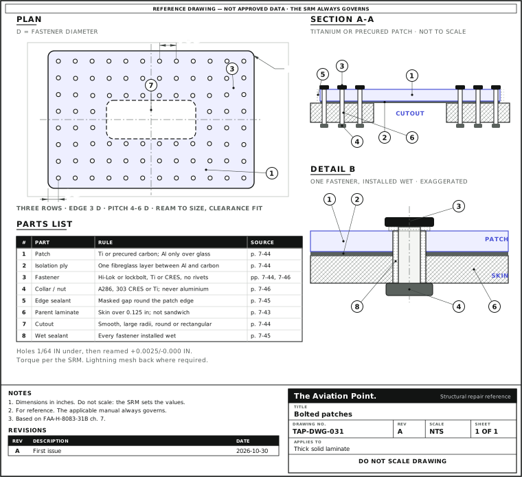
Lay out a bolted patch, one step at a time
| Step | Action | What to do |
|---|---|---|
| 1 | Draw the centrelines | Lay out two perpendicular centrelines on the parent structure and on the patch, along the main load directions. |
| 2 | Drill and transfer | Drill pilot holes in the patch, then transfer them to the parent with clecos. Mark the patch edge so it returns to the same place. |
| 3 | Open the holes | Back the composite so it does not split as the drill exits. Open the holes undersize, then ream to size. |
| 4 | Measure each grip | Use a grip gauge on every hole. |
| 5 | Install wet | Install every fastener wet with sealant, and torque as the SRM says. |
| 6 | Seal and finish | Seal the patch edge too, then prime and paint with the approved system. |
Bolted or bonded?
| Question | Bolted patch | Bonded patch |
|---|---|---|
| Laminate thickness | Normally skins thicker than 0.125 in, so the fasteners have enough bearing area | Thin laminates and lightly loaded parts |
| Honeycomb sandwich | Prohibited: holes let moisture in and the core degrades | Scarf or external step patch |
| Weight | Heavier than a bonded repair; a problem on flight control surfaces | Lighter |
| Materials | Patch and fasteners only; no freezer, no cure | Prepreg and film adhesive need cold storage and a cure |
| Stress concentration | Every hole adds one | None from fastener holes |
FAA-H-8083-31B Vol. 1 pp. 7-43 and 7-44, bonded versus bolted repairs and figure 7-74. Highly loaded laminates up to about 1 in thick cannot be scarfed; that is where bolted patches were developed.
Which repair fits?
The damage is in a honeycomb sandwich panel. Which patch fits?
- A bolted patch
Not this one. Bolting is prohibited here: the holes let moisture in and the core degrades.
- A riveted patch
Not this one. The handbook asks for no rivets on these patches.
- A bonded scarf or external step patch
Best fit. That is the bonded answer for a honeycomb sandwich.
On a real job, the SRM decides.
Patch and fastener: what goes with carbon
| Item | Use | Avoid |
|---|---|---|
| Patch, highly loaded part | Titanium or precured carbon/epoxy (same strength and stiffness as the parent when cured alike) | Aluminium on its own |
| Patch, aluminium on carbon | Allowed, with one layer of fibreglass cloth between patch and carbon | Aluminium touching carbon: galvanic corrosion |
| Fasteners in carbon | Titanium (Ti-6Al-4V is the most common) or stainless steel; A286 and MP35N also compatible | Aluminium fasteners, cadmium plating |
| Hi-Lok collars | A286, 303 stainless or titanium | Aluminium collars |
| Lockbolts | Hat-shaped collar with a flange; pin with six grooves for composite (five for metal) | Standard metal-structure collar |
| Rivets | None | A rivet gun damages the hole and the rivet expands, which can delaminate the laminate |
FAA-H-8083-31B Vol. 1 pp. 7-44 to 7-46. Fibreglass and aramid laminates do not corrode with most fastener metals; carbon is cathodic against aluminium and cadmium.
Holes: spacing, edge distance and reaming
Lay out two perpendicular centrelines on the parent structure and on the patch along the main load directions, drill pilot holes in the patch, then transfer them to the parent with clecos. Mark the patch edge so it returns to the same place.
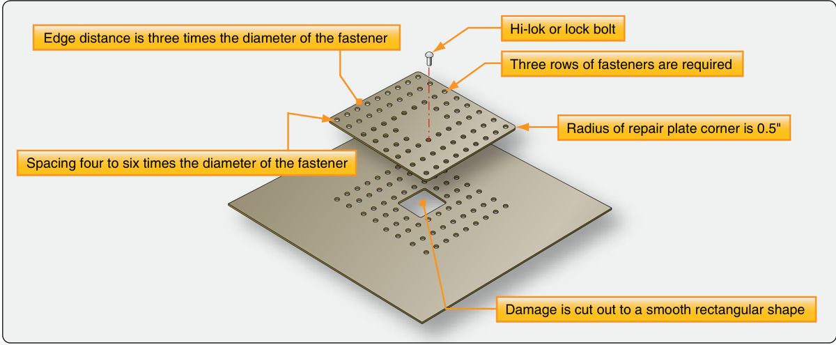
The handbook's composite rules are wider than the metal rules: holes at least 4 fastener diameters from existing fasteners and at least 3 diameters from the edge, against 2 diameters for aluminium. Figure 7-75 shows three rows of fasteners, 4 to 6 diameters between holes, and a patch corner radius of 0.5 in over a cutout trimmed to a smooth round or rectangular shape with large radii.
Back the composite so it does not split as the drill exits. Open the pilot holes 1/64 in undersize, then ream to size. The usual tolerance is +0.0025/-0.000 in, a clearance fit: interference fasteners are not used. Measure each grip with a grip gauge. Use diamond or carbide tools, air-driven if possible: carbon dust is conductive and enclosed motors are needed otherwise.
Sealing and finishing
Install every fastener wet with sealant and torque screws and bolts as the SRM says. Seal the patch edge too: mask a line parallel to the edge, leave a small gap and run sealant into it. The sealant keeps out water and fuel, stops galvanic corrosion and smooths the contour. Then prime and paint with the approved system.
If a composite patch sits in an area prone to lightning strike, the lightning mesh goes back on. See lightning strike protection repairs.
Questions people actually ask
Can I rivet a composite patch?
No. The handbook says rivets cannot be used: the gun damages the hole and the expanding rivet can delaminate the laminate. Use bolts or lockbolts that the SRM lists.
Can an aluminium patch go on carbon?
Yes, with a layer of fibreglass cloth between them, and with titanium or stainless fasteners. Titanium or precured composite patches are preferred when the part is highly loaded.
Why not bolt a honeycomb panel?
The thin face sheets have low bearing strength, drilling weakens the core, and the holes let moisture in. The handbook prohibits bolted repairs in sandwich assemblies.
How thick must the laminate be?
The handbook says bolted repairs are normally used on skins thicker than 0.125 in. Your SRM sets the actual minimum.
Limits of this guide
What the sources support, and no further.
- The pattern is not here. Number of rows, fastener type and diameter, patch thickness and torque come from the SRM or the design approval. The 3-4-6 diameter figures are the handbook's generic layout.
- Not covered. Bonded patches (see the scarf and repair-plies guides), fatigue and bearing allowables, and thick-laminate repair design.
- Pilot and drill sizes are the SRM's; the handbook gives only the 1/64 in undersize and reaming rule.
Where to buy
Distributors coming soon.
Sources
- FAA-H-8083-31B, AMT Handbook — Airframe, Volume 1 (2023), Chapter 7 — pp. 7-43 to 7-44, bonded versus bolted repair, patch materials, repair procedure steps 1 to 5; pp. 7-44 to 7-45, hole spacing and edge distance, reaming, figure 7-75, steps 6 to 8; pp. 7-45 to 7-46, corrosion precautions and fastener materials, Hi-Lok and Huck-Spin lockbolts; p. 7-19, air tools; p. 7-52, cutters for carbon, glass and aramid.