Reading a layup: the stack, the clock and the mirror
Where to buy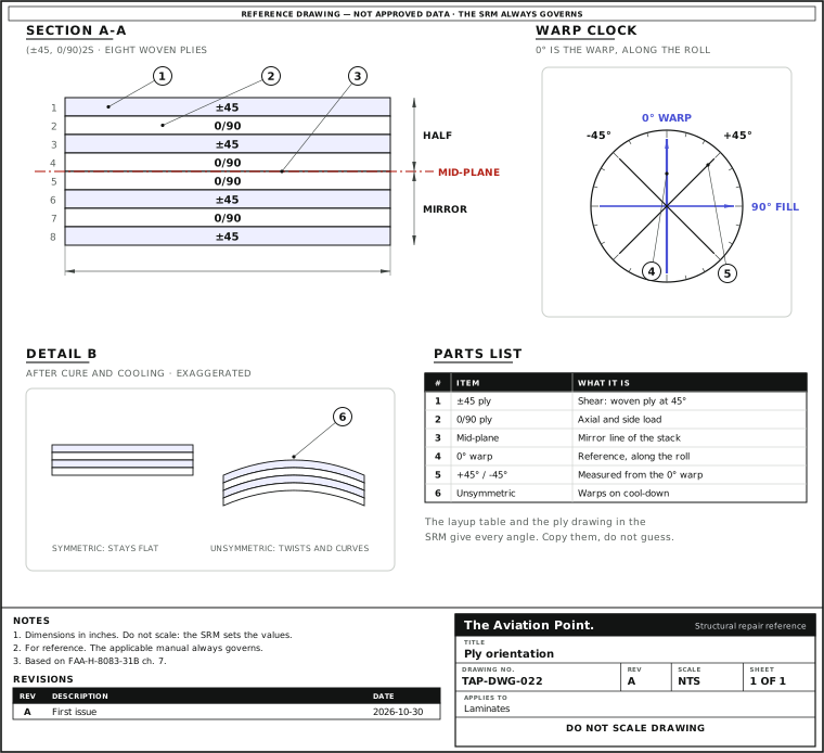
Match a repair ply, one step at a time
| Step | Action | What to do |
|---|---|---|
| 1 | Read the skin identification | It gives the number of plies, the orientation and the material. |
| 2 | Mark the directions | Mark the roll direction on the fabric before you cut, and the zero direction on the part. |
| 3 | Cut each ply | Use the same material and the same orientation as the ply it replaces, or a substitute the manufacturer approves. |
| 4 | Label and sort | Sort the cut plies by ply number and mark the direction on each. |
| 5 | Keep the stack symmetric | Work from the repair drawing, not from the look of the old plies. Where the SRM says more, it governs. |
What each angle does
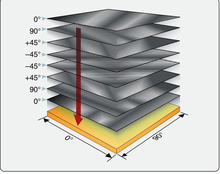
The Handbook: a part may need 0° plies to react to axial loads, ±45° plies to react to shear loads, and 90° plies to react to side loads. Because the design depends on the load direction, ply orientation and ply sequence have to be correct (p. 7-2).
Unidirectional tape is strong only along the fibre, with virtually no strength across it (p. 7-3). Woven fabric has strength in both directions, but not necessarily the same in each (p. 7-2).
Quasi-isotropic stacks of 0°, –45°, 45° and 90°, or of 0°, –60° and 60°, imitate an isotropic material, and many aerospace composite structures are made that way (p. 7-2).
The orientation alone moves carbon epoxy from stiffness near fiberglass to stiffness near titanium (p. 7-2): one reason an angle error is not cosmetic.
The warp clock
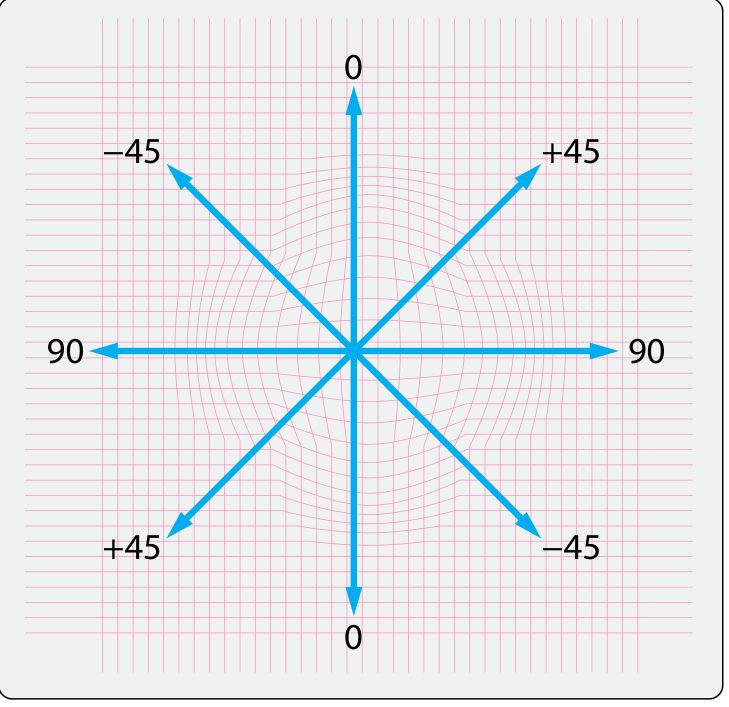
Warp means the fibres that run along the fabric. They are straight, so warp is the high-strength direction. A warp clock is the drawing that gives fibre directions on a diagram, spec sheet or the maker's sheet (p. 7-29).
Zero is the warp. If the fabric carries no warp clock, 0° is the direction it leaves the roll, and 90° is across its width (pp. 7-2, 7-29). So the roll direction decides every angle: mark it on the fabric before you cut, and mark the part's zero direction on the part.
Angles in a layup code are measured from the part's zero direction, which the SRM defines. A ply cut at the wrong 45° (clockwise instead of anticlockwise) is not the same ply for a unidirectional tape, even though it looks right.
How a layup is written
| Written as | Reads as, outer ply first | Plies | Made from |
|---|---|---|---|
| (+45, –45, 0)S | +45, –45, 0, 0, –45, +45 | 6 | Unidirectional tape |
| (±45, 0/90)2S | ±45, 0/90, ±45, 0/90, 0/90, ±45, 0/90, ±45 | 8 | Woven cloth, quasi-isotropic |
| ([±45]2, 0/90)S | ±45, ±45, 0/90, 0/90, ±45, ±45 | 6 | Woven cloth, quasi-isotropic |
FAA-H-8083-31B Vol. 1 p. 7-29, figure 7-49. Subscript S means the list is repeated in reverse to mirror it; a subscript 2 repeats the group in brackets or before it. A slash (0/90) and a plus-minus sign name the two fibre directions of a woven ply. Makers use other conventions: the SRM key governs.
Symmetric and balanced: what an unsymmetric stack does
| Type | Example | Effect when cured |
|---|---|---|
| Symmetric, balanced | (+45, –45, 0, 0, –45, +45) | Flat, constant mid-plane stress |
| Unsymmetric, balanced | (90, +45, 0, 90, –45, 0) | Induces curvature |
| Symmetric, not balanced | (–45, 0, 0, –45) | Induces twist |
| Unsymmetric, not balanced | (90, –45, 0, 90, –45, 0) | Induces twist and curvature |
FAA-H-8083-31B Vol. 1 p. 7-29, figure 7-50. The Handbook calls a symmetric or balanced laminate good practice to minimise the residual thermal stress from cure. The effect is largest in laminates cured hot, from the stress as they cool from cure temperature; a room-temperature wet layup distorts much less.
Matching each repair ply
Replace each damaged ply with a ply of the same material and the same orientation, or a substitute the manufacturer approves (Handbook pp. 7-2, 7-29; AC 43.13-1B para. 3-1a). The AC's glass patches go in with their fibres “lined up with the original fiber-orientation” (para. 3-2c).
Keep the stack symmetric. The AC's own scarf drawing is a symmetrical layup, the original number of plies plus one extra ply (para. 3-3a, figure 3-6). Where the SRM says more, it governs.
Work from the SRM's skin identification for the number of plies, orientation and material (Handbook figure 7-60). The Handbook's repair plies are drawn with a ply-locating template and the part's zero direction (figure 7-46): cut and place from that, not from the look of the old plies.
Sort the cut plies by ply number and mark the direction on each (shop practice). The repair plies guide sizes each ply; this one decides which way it points.
Worked example: read a layup, make the cut list
Parent skin written (±45, 0/90)2S, woven carbon, from the SRM. An invented case to show the reading, not a repair.
- Expand it: (±45, 0/90) twice, then the same four plies reversed. That is 8 plies: ±45, 0/90, ±45, 0/90, 0/90, ±45, 0/90, ±45.
- Check it mirrors about the middle: ply 1 = ply 8, ply 2 = ply 7, ply 3 = ply 6, ply 4 = ply 5. It does, so it is symmetric.
- Say plies 1 and 2 are damaged. The repair replaces one ±45 ply and one 0/90 ply, in that order from the outside, each cut with its warp on the part's zero or at 45° to it, as the layup says.
- Label each cut ply with number, angle and the warp direction before laying up. Add the extra ply only if the SRM calls for it.
Two plies to cut: ply 1 at ±45, ply 2 at 0/90, both from the same woven material as the original.
For UAV, model and homebuilt work
Many small parts are a few plies of woven cloth, often with the fabric at 45° to the part for torsion and at 0° for bending. The same rules hold: mark the roll direction, mirror the stack about its middle, and keep a drawing of what angle each ply took before you cut it.
Questions people actually ask
What does a layup written (±45, 0/90)2S mean?
A mirrored stack of eight woven plies: the group ±45, 0/90 twice, then the same four reversed (Handbook figure 7-49).
Why must the stack be symmetric?
A symmetric or balanced laminate minimises the residual thermal stress from cure. An unsymmetric one curves or twists, mostly when cured hot (Handbook p. 7-29, figure 7-50).
What if the fabric has no warp marking?
Then 0° is the direction it comes off the roll, and 90° is across the width (Handbook p. 7-29). Mark it before you cut.
Can I use a 0/90 ply where the original has ±45?
No, not on your own. The ply is replaced with the same material and orientation, or a substitute the manufacturer approves (Handbook p. 7-29).
Limits of this guide
What the sources support, and no further.
- The manual governs. Ply angles, sequence and any allowed substitute come from the SRM repair drawing and layup table.
- Notation varies. The code in figure 7-49 is the Handbook's; makers write layups differently, so read their key.
- The example is invented. It shows the reading of a code, not a repair design.
Where to buy
Distributors coming soon.
Sources
- FAA-H-8083-31B, AMT Handbook — Airframe, Volume 1 (2023), Chapter 7 — pp. 7-2 to 7-3, strength characteristics, fibre orientation, quasi-isotropic layups, warp clock (figures 7-1 to 7-3); pp. 7-28 to 7-29, balanced laminates, layup codes, effects of nonsymmetrical laminates (figures 7-46, 7-49, 7-50), warp.
- AC 43.13-1B, Change 1, Chapter 3, Fiberglass and Plastics — para. 3-1a, replacement material; para. 3-2c, fibre orientation; para. 3-3a, scarf repair, symmetrical layup plus one extra ply (figure 3-6).