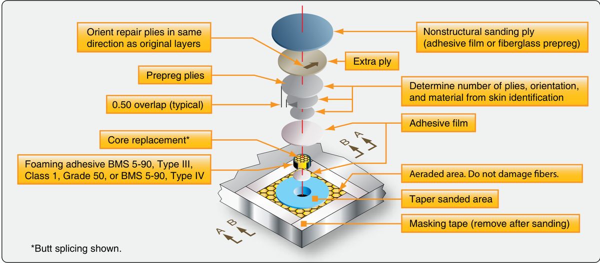
A scarf repair, ply by ply
Where to buy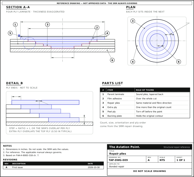
Check a cut list, one step at a time
| Step | Action | What to do |
|---|---|---|
| 1 | Read the repair data | Take the material, the count, the direction and the order from the SRM repair drawing. |
| 2 | Find the step per ply | It is the taper ratio times the cured ply thickness, or the overlap the SRM prescribes. |
| 3 | Size each ply | Each ply covers the opening at its own level. Cut to the sizes in the repair data, not to the size of the damage. |
| 4 | Check the direction | Each ply is laid in the same direction as the ply it replaces. |
| 5 | Check the order | The SRM names the sequence. A different one is a change to the repair. |
Seven rules for the cut list
| Rule | What the sources say | Where |
|---|---|---|
| Material | Same reinforcement as the original: same fabric or tape, same resin system or one the manufacturer approves. | H-8083-31B p. 7-39; AC 43.13-1B p. 3-1 |
| Fibre direction | Each repair ply is laid in the same direction as the ply it replaces. | H-8083-31B pp. 7-36, 7-39 |
| Count | The original plies, found from the skin identification, plus one extra ply. | H-8083-31B p. 7-36; AC p. 3-4 |
| Size | Each ply overlaps the one below by 0.50 in typical (Handbook figure); at least 1/2 in for the fiberglass patches of the AC. | H-8083-31B p. 7-36; AC p. 3-4 |
| Order | Smallest ply first is usual but leaves resin-rich ply edges; largest ply first, covering the whole work area, gives a stronger interface. Follow the SRM. | H-8083-31B p. 7-39; AC p. 3-4 |
| Symmetry | The layup mirrors the original, plus the one extra ply. | AC p. 3-4 (fig. 3-6) |
| Proof | Cure test specimens with the repair: same adhesive batch, same pressure, temperature and time. | AC p. 3-1 |
The AC repairs apply to fiberglass laminate for non-structural fairings, covers, cowlings and honeycomb panel facings. The AC says not to use them on radomes, graphite or Kevlar. The Handbook steps are not a substitute for the SRM.
From step to ply diameter
Every scarf repair has a step per ply: the taper ratio times the cured ply thickness, or the overlap the SRM prescribes. The Handbook gives both ways: “a taper ratio, such as 1:40”, or “a 1-inch overlap for each existing ply” (p. 7-35).
Ply k, counted from the bottom, covers the opening at its own level: hole + 2 × k × step. The extra ply on top is the top repair ply plus twice the overlap. The scarf repair calculator does the arithmetic and draws it.
Cut the plies to the sizes in the repair data, not to the size of the damage.
Worked example
Four plies, 0.0075 in cured each, a damage cleaned up to a 2 in hole, taper 1:40 and a 0.50 in overlap for the extra ply. A made-up case to show the arithmetic; the numbers come from your SRM.
- Step per ply = 40 × 0.0075 = 0.300 in.
- Ply 1 = 2 + 2 × 1 × 0.300 = 2.600 in; ply 4 = 2 + 2 × 4 × 0.300 = 4.400 in.
- Extra ply = 4.400 + 2 × 0.50 = 5.400 in.
- Five plies to cut: 2.600, 3.200, 3.800, 4.400 and 5.400 in, each in the fibre direction of the ply it replaces.
Four plies from Ø 2.600 to Ø 4.400 in, plus a Ø 5.400 in extra ply on top.
Which ply goes in first
Smallest first is the usual sequence and what most repair drawings show. It builds the repair in the order of the cut-out: the first ply sits at the bottom of the scarf. The price is a resin-rich pocket at each ply edge.
Largest first lays one ply that covers the whole work area, then smaller ones on it. The Handbook says it “produces a stronger interface joint”. The AC also calls this “an alternate layup method that works equally well” for fiberglass. It is not yours to choose: the SRM names the sequence, and a different one is a change to the repair.
Wet layup: cutting and resin
Impregnate the fabric on a sheet of peel ply and cover it with a second sheet before cutting. The AC does this so the patch does not ravel when cut (p. 3-4).
A resin weight equal to the cloth weight gives the 50 percent ratio the AC uses for fiberglass patches (p. 3-3). The laminate plies calculator works out the resin for a given fabric weight.
Prepreg is stored in a freezer below 0 °F (Handbook p. 7-25); log its out-time with the out-time calculator.
Questions people actually ask
Why one extra ply?
The Handbook says that “typically, one more ply than the original number of plies is installed”, and the AC adds the extra ply “to restore original strength”. It makes up for the loss in the bond line. Your SRM says whether it applies.
Can I use a different fabric if it is stronger?
No, not on your own. The Handbook asks for fabric “identical to the reinforcement material used in the original”, and the AC for identical chemical composition or a substitute the manufacturer approves.
Do the plies go on the front and back of a sandwich panel?
Each face sheet is repaired on its own. After the top skin is hard, the AC repeats the process on the bottom.
How do I know the original ply count?
From the skin identification in the SRM, or from the repair drawing. Counting plies by eye on a sanded edge is a check, not the source.
Limits of this guide
What the sources support, and no further.
- The manual governs. Count, size, orientation, ply order and material come from the SRM repair drawing.
- Scope of the AC. Its fiberglass repairs do not cover radomes or advanced composites (graphite, Kevlar), and its step and scarf numbers are not for load-carrying structure.
- The example is arithmetic. It is not a design: no ratio, overlap or ply count here is a recommendation.
Where to buy
Distributors coming soon.
Sources
- FAA-H-8083-31B, AMT Handbook — Airframe, Volume 1 (2023), Chapter 7 — p. 7-35, taper ratio such as 1:40 or a 1-inch overlap for each ply; p. 7-36, one more ply than the original, extra ply, orientation, 0.50 overlap (typical), smallest-ply-first; p. 7-39, step 5, largest ply first and identical reinforcement.
- AC 43.13-1B, Change 1, Chapter 3, Fiberglass and Plastics — p. 3-1, materials, test specimens; p. 3-3, resin 50 percent, scarf; p. 3-4, overlap at least 1/2 in, extra ply, peel ply sandwich, alternate layup.