What ASNA is, and why units come first
Where to buyASNA is a series of aircraft-manufacturer standards for fasteners. Its blind bolts and rivets are the ones you meet on aircraft built or repaired to the maker's drawings: Maxibolt-type bolts in steel and in titanium, CherryMAX-type rivets, Jo-Bolt-type threaded bolts, Composi-Lok and Radial-Lok bolts for composite, and a metric solid rivet. A number is a code, and the code counts in a unit the standard rarely names.
This guide reads the number segment by segment, gives every size inch first and millimetres after, and says where each unit comes from: printed in mm, code in 1/32 in, or no unit printed: our conversion. Where a source gives no unit, the guide does not assume one. Drill sizes always come from the drill chart, never from the nominal. The aircraft's maintenance manual and the current issue of the standard always govern.
Unit traps: read these first
| Trap | What the standard prints | What it means |
|---|---|---|
| Inch codes | Inch codes, millimetre tables: diameter and grip codes sit beside rounded mm values, and the unit of the code is rarely named. | On the blind fasteners of US origin (CherryMAX, Maxibolt, Jo-Bolt and Composi-Lok types) the diameter code counts 1/32 in and the grip code 1/16 in. Treat the mm as a printed conversion, not as the size. |
| Maxibolt code 05 | One code, four diameters: it appears as 3.97, 4, 4,0 and 4,14. | 3.97 mm is the nominal 5/32 in (0.156 in) and is printed with no unit. 4,14 mm is the real body, 0.163 in, printed in mm. 4 and 4,0 are rounded names. The hole comes from the hole table, 0.164–0.167 in. Never drill 5/32 in. |
| Grip codes | Grip codes do not travel: code 04 means something different in three families. | CherryMAX type: 0.188–0.250 in (4.78–6.35 mm). Maxibolt type: 0.219–0.282 in (5.56–7.16 mm), shifted 1/32 in. Jo-Bolt type: 0.220–0.281 in (5.59–7.14 mm). Composi-Lok: the code is the maximum grip in thousandths of an inch (150 = 0.150 in, our reading). Radial-Lok follows another rule. |
| Metric solid rivets | ASNA2049, 2050 and 2051 list 4 and 4,8 only. The drill and shop-head table they share with other standards also runs through 2,4 and 3,2. | These are millimetres. 4 means 4 mm (0.157 in), close to 5/32 in; it is never dash -4, which is 1/8 in (0.125 in). |
| Jo-Bolt marks | Diameter marks 2 to 6 are size indices. | Not mm and not 1/32 in. Mark 2 = 4.15 mm (0.163 in, #8 class), 3 = 4.8 mm (0.189 in, #10 class), 4 = 6.3 mm (1/4 in), 5 = 7.89 mm (5/16 in), 6 = 9.49 mm (3/8 in). The diameter header prints no unit: the inch sizes are our reading. |
| Tenths of a mm | European partners count tenths of a millimetre: PAN3614-40-06, MBBN3012L3202, ABS0112-24. | 40 = 4.0 mm, 32 = 3.2 mm, 24 = 2.4 mm. Never read those digits as 1/32-in dashes. The oversize MBBN 36 = 3.6 mm is 1/8 in + 1/64 in. |
| No unit printed | Figures with no unit: edge distance, pitch, distance to a bend, gauge steps (+,000 / +,058), Jo-Bolt stem position B. | Published as «unit not stated». This guide shows them as printed and, where it converts, says so. A figure with no unit is never converted in silence. |
| Cross-only numbers | Washers and the cross-only numbers: ASNA2397; ASNA0061 to 0064; ASNA0079 and 0080. | ASNA2397 follows the AN960 dash logic (inch, by equivalence). ASNA0061–0064 pair digit for digit with NAS1398, NAS1399, NAS1738 and NAS1739 (inch), but no source states their unit. ASNA0079 and 0080 do not decode: only the cross is shown. |
Inch values are our arithmetic (mm ÷ 25.4, or n/32 in, n/16 in) and are labelled as conversions. Source data: the ASNA standards, as transcribed and checked by The Aviation Point.
Reading an ASNA number: ASNA0026SA0506
A blind bolt number is built in segments. Take ASNA0026SA0506: the standard, a type letter, a material letter, a two-digit diameter code and a two-digit grip code. The part number decoder and the Cherry pulling head selector read the same codes; this table shows what each segment says and how sure the reading is.
ASNA0026SA0506 segment by segment
| Segment | Meaning | Size and where the unit comes from | Confidence |
|---|---|---|---|
| ASNA0026 | Maxibolt-type blind bolt, alloy steel or stainless, 100° countersunk head | — | High |
| S | With driving cap or washer, single-action installation, pulled with -MB heads. U = without washer, -MBU heads | — | High |
| A | Alloy steel, 112 ksi class. B = A-286 stainless, 95 ksi class. The A and U readings come from the partner standards (MS90353, CR7310): confirm them on the standard | — | Medium |
| 05 | Diameter code 05 | Nominal 5/32 in (0.156 in; 3.97 mm printed with no unit). Body 0.163 in (4.14 mm, printed in mm). Hole 0.164–0.167 in (4.16–4.24 mm†). Largest countersink Ø 0.334 in (8.48 mm†) | High |
| 06 | Grip code 06 | 0.344–0.407 in (8.74–10.34 mm, printed in mm). The same range as grip 06 of MS90353 (.344–.407 in) | High |
Unit marks: no mark = the standard prints the figure in mm and says so. † = the standard prints the figure with no unit; the inch value is our conversion, reading the figure as mm because the columns beside it are in mm. Fractions are our reading of the inch code (1/32 in). Equivalents: MS90353S0506 and CR7310S-05-06 (distributor listings, medium), SB100-T05-06 (same NSN as CR7310S-5-06), PAN3614-40-06 (low: PAN writes 4,0 mm as 40). MS90353U0506W is the U type, so it is not identical: it takes another pulling head.
ASNA numbers at a glance
| Standard | What it is | Head |
|---|---|---|
| ASNA0026 | Maxibolt-type blind bolt, alloy steel (A) or A-286 stainless (B) | 100° countersunk |
| ASNA0027 | Maxibolt-type blind bolt, alloy steel or stainless | Cylindrical, protruding |
| ASNA0341 | Maxibolt-type blind bolt, titanium | 100° countersunk |
| ASNA0342 | Maxibolt-type blind bolt, titanium | Cylindrical, protruding |
| ASNA0363 | Maxibolt-type blind bolt, titanium | Large flattened round, protruding |
| ASNA0077 · ASNA0078 | CherryMAX-type bulbed blind rivet, mechanically locked stem | 100° countersunk · protruding |
| ASNA0081 · ASNA0082 | Jo-Bolt-type self-locking threaded blind bolt | 100° countersunk · hexagon |
| ASNA0012 · ASNA0013 | Composi-Lok-type titanium blind bolt for composite structure | 100° countersunk · protruding |
| ASNA302 · ASNA303 | Radial-Lok-type titanium blind bolt for composite structure | 100° countersunk · protruding |
| ASNA2049 · ASNA2050 · ASNA2051 | Metric solid rivet, 2017A-T4 (code DX) | Reduced 100° countersunk · protruding · 100° countersunk |
| Cross-only cards | ASNA0061, ASNA0062, ASNA0063, ASNA0064, ASNA0079, ASNA0080, ASNA2397: the partner numbers, no sizes | — |
Each number links to its data sheet: part numbers by size, hole, grip, tools and cross. The cross-only cards give the partner numbers and no sizes.
Maxibolt installed: flush heads, stem B and collar A
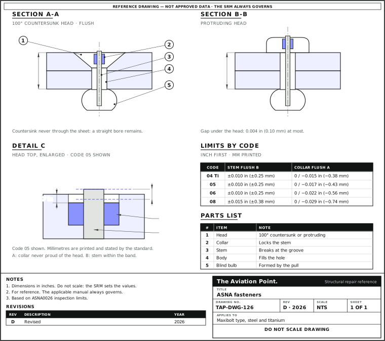
Maxibolt-type bolts in steel: ASNA0026 and ASNA0027
ASNA0026 (100° countersunk head) and ASNA0027 (cylindrical, protruding head) are blind bolts with a pulled stem and a locking collar, in alloy steel (A) or A-286 stainless (B). A C mark on the stem means a stainless stem; no mark, an alloy-steel stem. The diameter codes are 05, 06 and 08.
The body is bigger than the nominal fraction. The hole table, not the nominal, sets the drill. For the countersunk head, do not deburr the hole edge and countersink up to the largest diameter in the table; for the protruding head, deburr the hole edge up to the largest deburr diameter. The countersink must never go through the sheet: a straight bore of at least 0.008 in (0.2 mm, printed in mm) stays. The drill calculator does the lookup for a part number.
Maxibolt steel: diameter codes, hole and drill
| Code | Nominal (our reading of the code) | Body Ø | Hole | Drill, from the drill chart | Largest countersink Ø, ASNA0026 |
|---|---|---|---|---|---|
| 05 | 5/32 in (0.156 in; 3.97 mm) | 0.163 in (4.14 mm) | 0.164–0.167 in (4.16–4.24 mm†) | #19 (0.1660 in; 4.22 mm) | 0.334 in (8.48 mm†) |
| 06 | 3/16 in (0.188 in; 4.76 mm) | 0.198 in (5.03 mm) | 0.199–0.202 in (5.05–5.13 mm†) | #7 (0.2010 in; 5.11 mm) | 0.387 in (9.83 mm†) |
| 08 | 1/4 in (0.250 in; 6.35 mm) | 0.259 in (6.58 mm) | 0.260–0.263 in (6.60–6.68 mm†) | G (0.2610 in; 6.63 mm) | 0.508 in (12.90 mm†) |
Unit marks: no mark = the standard prints the figure in mm and says so. † = the standard prints the figure with no unit; the inch value is our conversion, reading the figure as mm because the columns beside it are in mm. Fractions are our reading of the inch code (1/32 in). ASNA0027 uses the same holes; its largest deburr diameters are 0.190 in (4.83 mm†), 0.235 in (5.97 mm†) and 0.296 in (7.52 mm†) for codes 05, 06 and 08.
Maxibolt grip codes, steel and titanium
| Grip code | Steel: ASNA0026, 0027 | Titanium: ASNA0341, 0342, 0363 |
|---|---|---|
| 01 | — | 0.093–0.157 in · 2.36–3.99 mm (unlabelled, overlaps 02) |
| 02 | 0.094–0.157 in · 2.39–3.98 mm (code 05) 0.120–0.157 in · 3.05–3.98 mm (code 06) | 0.120–0.157 in · 3.05–3.99 mm (overlaps 01) |
| 03 | 0.156–0.220 in · 3.96–5.59 mm | 0.156–0.220 in · 3.96–5.59 mm |
| 04 | 0.219–0.282 in · 5.56–7.16 mm | 0.219–0.282 in · 5.56–7.16 mm |
| 05 | 0.281–0.345 in · 7.14–8.76 mm | 0.281–0.345 in · 7.14–8.76 mm |
| 06 | 0.344–0.407 in · 8.74–10.34 mm | 0.344–0.407 in · 8.74–10.34 mm |
| 07 | 0.406–0.470 in · 10.31–11.94 mm | 0.406–0.470 in · 10.31–11.94 mm |
| 08 | 0.469–0.532 in · 11.91–13.51 mm | 0.469–0.532 in · 11.91–13.51 mm |
| 09 | 0.531–0.595 in · 13.49–15.11 mm | 0.531–0.595 in · 13.49–15.11 mm |
| 10 | 0.594–0.657 in · 15.09–16.68 mm | 0.594–0.656 in · 15.09–16.67 mm |
| 11 | 0.656–0.720 in · 16.66–18.29 mm | 0.656–0.720 in · 16.66–18.29 mm |
| 12 | 0.719–0.782 in · 18.26–19.86 mm | 0.719–0.782 in · 18.26–19.86 mm |
| 13 | 0.781–0.845 in · 19.84–21.46 mm | 0.781–0.845 in · 19.84–21.46 mm |
| 14 | 0.844–0.907 in · 21.44–23.03 mm | 0.844–0.907 in · 21.44–23.04 mm |
| 15 | — | 0.906–0.970 in · 23.01–24.64 mm |
| 16 | — | 0.969–1.032 in · 24.61–26.21 mm |
Grip ranges are printed in mm (stated) with the inch value converted. The Maxibolt grip code n is shifted 1/32 in against the Cherry-type codes. Lengths in work documents are indicative: measure the stack with a grip gauge. In the steel table grip 02 splits by diameter code; in the titanium table rows 01 and 02 overlap without a diameter label.
Titanium Maxibolt: ASNA0341, ASNA0342, ASNA0363
Read the number as ASNA0341T0506: standard, the letter T, diameter code 05 (5/32 in nominal, hole 0.164–0.167 in), grip code 06 (0.344–0.407 in, 8.74–10.34 mm printed). An optional final R is a procurement letter for parts supplied without the anvil. Stem heads carry three marks: material on the left, maker on top and the grip at the lower right.
Diameter code 04 (1/8 in nominal) exists on ASNA0341: body 0.128 in (3.25 mm printed in mm), hole 0.129–0.132 in (3.28–3.35 mm†), largest countersink Ø 0.229 in (5.82 mm†). It is pulled with the -456 heads on a G704B or G747 (see the tools table); the stem flush limit is ±0.010 in (±0.25 mm) and the collar flush 0 / −0.015 in (−0.38 mm), both printed in mm. The ASNA0342 and ASNA0363 tables list 05, 06 and 08.
The -8 offset head. The standard's sheet gives no 90° head for the -8. The manufacturer's catalogue adds the H828-8MB on a G84 with adapter 744-200, for the titanium S type only; it must not be used on the steel -8.
Titanium Maxibolt: what to check before you order
| Point | What the data says | What to do |
|---|---|---|
| The letter T | The family title says titanium; the standard does not print what the letter stands for. | Read T as titanium and confirm on the standard. |
| Grips 01 and 02 | 01 is 0.093–0.157 in (2.36–3.99 mm) and 02 is 0.120–0.157 in (3.05–3.99 mm), with no diameter label. In the steel table the same split is by diameter 05 and 06. | Do not choose between 01 and 02 from the table: measure the stack and check the maker's table for your diameter. |
| Code 04 on ASNA0363 | A footnote allows code 04 on «ASNA0341 and ASNA0343». ASNA0343 is described nowhere and is most likely ASNA0363. Distributors list ASNA0363T0401. | Treat 04 on 0363 as probable and confirm before ordering. |
| Cross-reference | Only ASNA0341 has partners: CR7770S-…W and HS5913-…BS/BSU (distributor listings). ASNA0342 and ASNA0363 have none; there is no MS, NAS or BAC number in our data. | Order by the ASNA number. |
| Head dimensions | The standard data gives no head diameter or height for any ASNA blind bolt. | Take head dimensions from the drawing or the maker. |
Open points in the ASNA data.
CherryMAX-type rivets: ASNA0077 and ASNA0078
ASNA0077 (100° countersunk) and ASNA0078 (protruding) are bulbed blind rivets with a mechanically locked stem and a locking collar. The number is the standard, a material letter A to F, a one-digit diameter code, a two-digit grip code and an optional X for oversize (+1/64 in on the diameter). The letters map to the Cherry and NAS numbers the decoder already holds: A = CR3212/CR3213 (NAS9302B/9301B), B = CR3222/3223, C, D and E = Monel families, F = CR3552P. The head marks say more: a + is a stainless-steel stem with an aluminium-alloy sleeve, no mark a steel stem, an M a Monel sleeve, and an inverted T the oversize.
Grips start at 02 on ASNA0077 (no 01) and at 01 on ASNA0078; the first code has no minimum, and each code n above it tops out at n/16 in. For the grip and the part number of a stack use the CherryMAX grip selector. The countersink must not go through the sheet, with a small radius left at the cone-to-hole junction.
CherryMAX type: diameter codes, hole and drill
| Code | Nominal | Printed name | Hole | Drill, from the drill chart | Countersink Ø, 100° head |
|---|---|---|---|---|---|
| 4 | 1/8 in (0.1250 in) | 3.2 mm | 0.1291–0.1319 in (3.28–3.35 mm†) | #30 (0.1285 in; 3.26 mm), just under the minimum: gauge the hole | 0.222–0.228 in (5.64–5.79 mm†) |
| 5 | 5/32 in (0.1562 in) | 4 mm | 0.1602–0.1642 in (4.07–4.17 mm†) | #20 (0.1610 in; 4.09 mm) | 0.283–0.289 in (7.19–7.35 mm†) |
| 6 | 3/16 in (0.1875 in) | 4.8 mm | 0.1921–0.1961 in (4.88–4.98 mm†) | #10 (0.1935 in; 4.91 mm) | 0.350–0.356 in (8.89–9.04 mm†) |
Unit marks: no mark = the standard prints the figure in mm and says so. † = the standard prints the figure with no unit; the inch value is our conversion, reading the figure as mm because the columns beside it are in mm. Fractions are our reading of the inch code (1/32 in). The printed names 3,2 · 4 · 4,8 are in mm (stated in the tooling block): 3,2 mm is 1/8 in rounded. Code 4: the chart's #30 (0.1285 in) is just under the printed hole minimum (0.1291 in); a drill cuts slightly oversize, so gauge the finished hole.
Jo-Bolt-type bolts: ASNA0081 and ASNA0082
ASNA0081 (100° countersunk) and ASNA0082 (hexagon head) are self-locking threaded blind bolts made of a nut body, a sleeve and a threaded stem. The number is the standard, a material and protection code (a hyphen is alloy steel, A stainless, B or C titanium), a diameter mark 2 to 6, a grip mark and a locking type: W (lobed locking), Y (3 crimp points at 120°) or Z (the same plus a locking nut). A number with no locking type is prohibited. Grip marks run in 1/16 in steps (printed in mm); the countersunk head has no grip 01.
Heads carry four marks: the maker's monogram, a K for diameter marks 3 and 4, SL for self-locking, and a material symbol (a square for alloy steel, a dot for stainless, an X for titanium).
Jo-Bolt type: diameter marks, hole and drill
| Mark | Printed diameter | Inch size (our reading) | Hole | Drill, from the drill chart |
|---|---|---|---|---|
| 2 | 4.15 mm† | 0.163 in (0.164 in) | 0.165–0.167 in (4.19–4.23 mm†) | #19 (0.1660 in; 4.22 mm) |
| 3 | 4.8 mm† | 0.189 in (0.190 in) | 0.190–0.192 in (4.82–4.87 mm†) | #11 (0.1910 in; 4.85 mm) |
| 4 | 6.3 mm† | 0.248 in (1/4 in) | 0.249–0.251 in (6.32–6.37 mm†) | 1/4 in (0.2500 in; 6.35 mm) |
| 5 | 7.89 mm† | 0.311 in (5/16 in) | 0.311–0.313 in (7.91–7.96 mm†) | 5/16 in (0.3125 in; 7.94 mm) |
| 6 | 9.49 mm† | 0.374 in (3/8 in) | no hole row printed | — |
Unit marks: no mark = the standard prints the figure in mm and says so. † = the standard prints the figure with no unit; the inch value is our conversion, reading the figure as mm because the columns beside it are in mm. Fractions are our reading of the inch code (1/32 in). The diameter column prints no unit; the marks are size indices, not a unit.
Composi-Lok and Radial-Lok bolts for composite: ASNA0012, 0013, 302, 303
These titanium blind bolts are made for composite structure. ASNA0012 and ASNA0013 are Composi-Lok types (countersunk and protruding); ASNA302 and ASNA303 are Radial-Lok types. The number is the standard, a material letter (S is printed, without a meaning), a two-digit diameter code and a grip code of three or four digits.
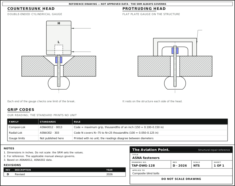
The grip code is not the Maxibolt one. On Composi-Lok it is the maximum grip in thousandths of an inch: 150 means 0.100–0.150 in (2.54–3.81 mm). On Radial-Lok, code N covers N−75 to N+25 thousandths in 0.100 in steps: 100 means 0.050–0.125 in. Both readings are ours, drawn from the computed ranges; the sheets print mm-like values with no unit.
Install with the pneumatic pistol-grip MP550RL, or the 90° MRT300 where access is restricted, and check the break with the H / L gauge shown below.
Composi-Lok and Radial-Lok: diameter codes, hole and drill
| Code | Nominal | Hole | Fastener Ø | Drill, from the drill chart |
|---|---|---|---|---|
| 5 | 5/32 in | 0.165–0.168 in (4.191–4.267 mm†) | 0.1645 in (4.178 mm†) | #19 (0.1660 in; 4.22 mm) |
| 6 | 3/16 in | 0.199–0.202 in (5.054–5.130 mm†) | 0.1985 in (5.041 mm†) | #7 (0.2010 in; 5.11 mm) |
| 8 | 1/4 in | 0.260–0.263 in (6.604–6.680 mm†) | 0.2595 in (6.591 mm†) | G (0.2610 in; 6.63 mm) |
Unit marks: no mark = the standard prints the figure in mm and says so. † = the standard prints the figure with no unit; the inch value is our conversion, reading the figure as mm because the columns beside it are in mm. Fractions are our reading of the inch code (1/32 in). Here the mm hole values equal the inch sizes exactly (0.165 in = 4.191 mm), so the inch figures are probably the origin.
Composi-Lok and Radial-Lok: the H / L gauge check
Metric solid rivets: ASNA2049, ASNA2050, ASNA2051
These are solid rivets in 2017A-T4 aluminium alloy (code DX) with a radiused shank end and a chemical conversion protection (J, Alodine type). ASNA2049 has a reduced 100° countersunk head, ASNA2050 a protruding head and ASNA2051 a 100° countersunk head. The protruding and reduced heads carry a raised rectangle-circle-rectangle mark; the standard countersunk head carries none. They replace the DE rivets, which were driven freshly quenched with a square shank end.
Length. L = E + K·D, with K = 1.3 for DX (1.5 for 2117 DC rivets, 0.8 for Monel TB), everything in mm. Do not cut these rivets to length. The diameters are metric: 4 means 4 mm. A #21 drill (0.1590 in, 4.04 mm) fits the DX 4 mm hole, but not the DC and TB 4 mm hole (0.159–0.163 in; 4.05–4.15 mm printed). The standards give no part-number construction, so their data sheets are partial.
ASNA2049, 2050, 2051 (DX): diameter, hole, drill and shop head
| Diameter | Inch | Hole | Drill, from the drill chart | Shop head (upset) |
|---|---|---|---|---|
| 4 mm | 0.158 in (nearest fraction 5/32 in) | 0.158–0.162 in (4.01–4.11 mm) | #21 (0.1590 in; 4.04 mm) | D 6.2–7.5 mm (0.244–0.295 in); H 1.3–2.2 mm (0.051–0.087 in) |
| 4.8 mm | 0.189 in (nearest fraction 3/16 in) | 0.189–0.193 in (4.80–4.90 mm) | #11 (0.1910 in; 4.85 mm) | D 7.3–8.7 mm (0.287–0.343 in); H 1.6–2.6 mm (0.063–0.102 in) |
Hole and shop-head sizes are printed in mm and stated. The ASNA range is 4 and 4,8 mm (millimetres; the inch columns are our conversion). The DX table the standards share with others also carries 2,4 and 3,2 mm: those are not ASNA2049, 2050 or 2051 sizes.
General riveting rules: C, P, B, wet fitting and countersinks
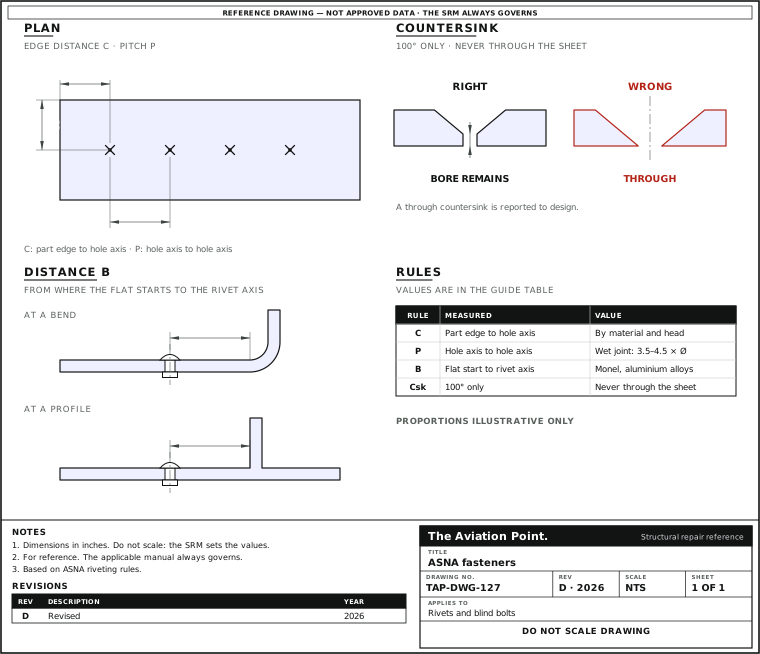
The rules below are the ASNA production values for edge distance C (part edge to hole axis), pitch P (hole axis to hole axis) and distance B (from the end of the inside bend radius, where the flat starts, to the rivet axis). The tables print them with no unit, under a column header in mm; the inch value is our conversion. Whether C is a minimum or a nominal is not stated. B has no values for steel, titanium, SL or Jo-Bolt.
Wet fitting. A few drops of sealant go under the manufactured head before the rivet is installed; after upsetting, a continuous bead must show all round the head. No sealant on the shank of a solid rivet, or it can tip over while driven. For sealed or wet joints the pitch is 3.5 to 4.5 × Ø when the stack is not thicker than Ø/2, and 4 to 5 × Ø above that (the standard's sealed rows use the letter P for the stack thickness, which is not the pitch P).
Countersinks are 100° only and never go through the sheet: a straight bore must remain, and a countersink that goes through is reported to design.
Edge distance C, pitch P and distance B by rivet diameter
| Rule | Ø 2.4 mm (0.094 in) | Ø 3.2 mm (0.126 in) | Ø 4 mm (0.157 in) | Ø 4.8 mm (0.189 in) |
|---|---|---|---|---|
| C: steel, Ti, Monel | 7 · 0.276 in | 8 · 0.315 in | 9 · 0.354 in | 11 · 0.433 in |
| C: aluminium alloy | 5.5 · 0.217 in | 7 · 0.276 in | 8 · 0.315 in | 9.5 · 0.374 in |
| C: SL, Jo-Bolt, 100° | — | — | — | 10 · 0.394 in |
| C: SL, Jo-Bolt, round | — | — | — | 9 · 0.354 in |
| P: minimum | 12 · 0.472 in | 13 · 0.512 in | 16 · 0.630 in | 20 · 0.787 in |
| P: standard | 20 · 0.787 in | 25 · 0.984 in | 30 · 1.181 in | 35 · 1.378 in |
| P: maximum | 25 · 0.984 in | 35 · 1.378 in | 40 · 1.575 in | 50 · 1.969 in |
| B: Monel | 4 · 0.157 in | 5 · 0.197 in | 6 · 0.236 in | 7 · 0.276 in |
| B: aluminium alloys | 3 · 0.118 in | 4 · 0.157 in | 5 · 0.197 in | 6 · 0.236 in |
C is the edge distance, P the pitch and B the distance to a bend or profile. The C rows for steel, titanium, Monel and aluminium-alloy rivets apply to 100° countersunk or flattened round heads; the SL and Jo-Bolt rows are the 100° countersunk and flattened round heads. Values in mm with the inch conversion, printed with no unit (the header says mm), so both are our reading: †. For general sheet-metal layout from the FAA handbook see the rivet layout guide.
C, P, B and the countersink: right and wrong
Tools by family and diameter
| Family | Standards · code | Tool | Straight head | 90° head | Offset head |
|---|---|---|---|---|---|
| CherryMAX type | ASNA0077, 0078 · 4, 5, 6 | G747 pneumatic (stroke 0.437 in = 11.1 mm printed); hand tool G27 for code 4 only | H701B-456, or H747-456 with insert 782-456 | H753A-456 | H782 + insert 782-456; H781-456 only where access forces it (nose setback L = rivet diameter, mandatory for code 4) |
| Maxibolt S | 04 (titanium only) | G704B or G747 | H701B-456 or H747-456 | H753A-456 | H782 + insert 782-456 |
| Maxibolt S | 05 | G83 (or G704B / G747 with the -456 heads above) | H83B-5MB | H828-5MB + adapter 744-300 | H782 + insert 782-456 + adapter 744-300 |
| Maxibolt S | 06 | G83 | H83B-6MB | H828-6MB + adapter 744-300 | H856-6MB + adapter 744-300 |
| Maxibolt S | 08 | G84 | H84A-8MB | none on the standard's sheet; titanium S only: H828-8MB on G84 + adapter 744-200 (manufacturer), never for the steel -8 | none |
| Maxibolt U | no washer · 05, 06, 08 | Same tool bodies as S, -MBU heads (manufacturer catalogue) | H83B-5MBU · H83B-6MBU · H84A-8MBU, H84C-8MBU, H84D-8MBU | H828-5MBU; H828-6MB with U nosepiece 828-036 | none |
| CherryLOCK A | ASNA0061, 0062 · 3, 4 | G747 or 746A; hand tool G30 | H747-3A + insert 782-3E | H753A-456 + insert 782-3E (grip code 4 maximum) | H782 + insert 782-3E |
| Composi-Lok, Radial-Lok | ASNA0012, 0013, 302, 303 · 5, 6, 8 | MP550RL pneumatic pistol-grip | MP550RL | MRT300 (restricted access) | none |
| Jo-Bolt type | ASNA0081, 0082 · 2 to 6 | The tool is not given in our data: use the maker's installation tool; the threaded stem is pulled until it breaks off | — | — | — |
| Solid rivets | ASNA2049, 2050, 2051 · all | Squeezing: pneumatic or manual squeezer. Percussion: rivet gun with rivet set and bucking bar | — | — | — |
From the standards' tooling tables and the maker's pulling-head sheets. Use the Cherry pulling head selector for a part number, and the pulling head guide for the heads. The G746A is recommended only for Maxibolt -4 and -5.
Inspection limits by family
| Family | Check | Limit, inch first | Unit source |
|---|---|---|---|
| CherryMAX, Maxibolt, Jo-Bolt | Gap under a protruding head | Not more than 0.004 in (0.10 mm) on more than 10 % of the row, and never on 2 consecutive fasteners. | mm, printed |
| CherryMAX, Maxibolt | Gap under a countersunk head | Not more than 0.004 in (0.10 mm) over more than half the periphery, on more than 20 % of the row, or on 2 consecutive fasteners. | mm, printed |
| CherryMAX, Maxibolt | Countersunk head flush | Ideal 0; accepted +0.05 / −0.10 | unit not stated (the other tolerances on the sheet are mm): not converted |
| CherryMAX | Stem and collar against the head top | Protrusion 0.25 maximum, recess 0.50 maximum (0.38 for code 4) | unit not stated (mm by context): not converted |
| Maxibolt | Stem flush B (measured on the break) | ±0.010 in (0.25 mm) for codes 04 to 06; ±0.015 in (0.38 mm) for code 08 | mm, printed |
| Maxibolt | Collar flush A (never proud) | 0 / −0.015 in (0.38 mm) (04, titanium); 0 / −0.017 in (0.43 mm) (05); 0 / −0.022 in (0.56 mm) (06); 0 / −0.029 in (0.74 mm) (08) | mm, printed |
| Jo-Bolt | Gap under hexagon head (A) / countersunk head (C) | 0.004 in (0.10 mm) maximum on no more than 10 % of the joint / 0.003 in (0.07 mm) maximum on no more than 20 % of the joint; never on 2 consecutive | mm, printed |
| Jo-Bolt (hexagon head) | Break-off gauge, stepped | Steps +,000 and +,058. A high break: the gauge must not rock. A low break: the gauge must be able to rock | unit not stated: not converted |
| Composi-Lok, Radial-Lok | Break check with the H / L gauge | Cylindrical double-ended gauge for countersunk heads, flat plate gauge for protruding heads. The H and L values are not published here: the standard prints them with no unit and our readings disagree | — |
| Solid rivets (DX) | Shop head D and H | See the table in the solid rivets section; two defective rivets must be separated by at least 5 good ones, and defects may affect under 5 % of structural rivets | mm, printed |
Limits as the standards give them; the aircraft's SRM governs. Inch values are our conversion of mm that the standard prints and states; figures with no unit are not converted.
Questions people actually ask
What does ASNA mean in a fastener number?
ASNA is a series of fastener standards written by an aircraft manufacturer. The digits after it name the standard, and the letters and digits after those are the variant: type, material, diameter and grip. The same numbers show up on drawings, in parts lists and on distributor sites, so a decoder saves a lookup.
Is ASNA0026 the same as MS90353 or CR7310?
They are partners, not twins. The grip table matches MS90353 digit for digit and the listings pair ASNA0026SA0506 with MS90353S0506 and CR7310S-05-06. Only a federal NSN record or a standard-level table proves that two numbers are the same part; a distributor pairing is an alternate.
Which drill do I use for ASNA0026SA0506?
Take the hole table: 0.164–0.167 in (4.16–4.24 mm). A #19 drill (0.1660 in, 4.22 mm) falls inside it. Do not drill 5/32 in: the Maxibolt body is 0.163 in, bigger than its nominal. The drill calculator does this lookup from the part number.
Can I use the CherryMAX grip table for a Maxibolt?
No. Grip code 04 is 0.188–0.250 in on a CherryMAX type, 0.219–0.282 in on a Maxibolt type and 0.220–0.281 in on a Jo-Bolt type. Use the grip table of the family you are fitting, and measure the stack with a grip gauge.
Does ASNA0363 come in diameter 04?
It is probable but not confirmed. The standard data lists 04 for ASNA0341 and mentions it for a number written ASNA0343 that most likely means ASNA0363; a distributor lists ASNA0363T0401. Confirm before ordering.
What does 4 mean on an ASNA2049 rivet?
4 mm, which is 0.157 in. The ASNA solid rivets are metric: 4 mm is close to 5/32 in, and it is never the dash -4 of the inch series, which is 1/8 in. They are DX rivets, so L = E + 1.3·D and they are never cut to length.
Limits of this guide
What the sources support, and no further.
- Reference data, not approved data. The ASNA standards are the manufacturer's own documents. This guide uses a verified reference package built from them and does not reproduce their text; the current issue and the SRM govern.
- Two Maxibolt letters are read, not printed. A (alloy steel, 112 ksi class) and U (no washer) come from the partner standards MS90353, CR7310 and the maker's -MBU heads.
- Not covered. Head dimensions, extraction procedures, heat treatment and finishes of the ASNA fasteners: the standard data holds none. Gauge limits for the composite bolts and the stem-position table of the Jo-Bolt are on the data sheets or in the maker's data.
- Cross-reference. Partner numbers are ranked by evidence: federal NSN record, manufacturer catalogue, distributor listing. A listing can pair a countersunk number with a protruding rivet, or the other way round: check head and size on both sides before accepting a cross-reference. A distributor pairing is an alternate, never proof of identity.
Where to buy
Distributors coming soon.
Keep going
Calculators
Guides
How to do it
Tools
Data sheets
Books
Buy
Distributors coming soon.
Sources
- ASNA standards: ASNA0012, 0013, 0026, 0027, 0077, 0078, 0081, 0082, 0341, 0342, 0363, 302, 303, 2049, 2050, 2051 — Codes, hole and grip tables, tooling and inspection limits, transcribed into the reference data of The Aviation Point. The text of the standards is not reproduced; check the issue in force on your own document system.
- Cherry Aerospace pulling-head sheets — -MBU heads for the U type and the titanium -8 offset head; the same data feeds the Cherry pulling head selector.
- US federal item records (DLA, NSN) and distributor listings — Partner numbers: MS90353, MS21140, CR7310, CR7620, CR7770, BACB30VX, BACR15 and others. The evidence is named on each cross line.
- FAA-H-8083-31B, Aviation Maintenance Technician Handbook: Airframe, Chapter 4 — General rivet layout and drill sizes, used for the context and for the drill chart.