ASNA0027 at a glance
Where to buy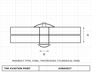
Specification
| Item | Value |
|---|---|
| Type | Blind bolt, pulled stem with locking collar |
| Material | Alloy steel (A) or A-286 stainless (B); stem mark C = stainless stem, no mark = alloy-steel stem |
| Strength | A: 112 ksi class; B: 95 ksi class (the standard prints 95 KSI without naming the property) |
| Item | Value |
|---|---|
| Locking | Pulled stem with a locking collar; the collar must never stand beyond the stem after the break |
| Finish | Not stated in the standard data |
| Status | Reference data transcribed from the standard, units marked row by row. Check the issue of the standard in force before design use. |
Dimensions by size
| Dimension, inch first (mm after) | -05 | -06 | -08 |
|---|---|---|---|
| Nominal Ø (code) | 5/32 in (0.156 in; 3.97 mm) | 3/16 in (0.188 in; 4.76 mm) | 1/4 in (0.250 in; 6.35 mm) |
| Body Ø | 0.163 in (4.14 mm) | 0.198 in (5.03 mm) | 0.259 in (6.58 mm) |
| Hole † | 0.164–0.167 in (4.16–4.24 mm†) | 0.199–0.202 in (5.05–5.13 mm†) | 0.260–0.263 in (6.60–6.68 mm†) |
| Drill (chart) | #19 (0.1660 in; 4.22 mm) | #7 (0.2010 in; 5.11 mm) | G (0.2610 in; 6.63 mm) |
| Max deburr Ø † | 0.190 in (4.83 mm†) | 0.235 in (5.97 mm†) | 0.296 in (7.52 mm†) |
Units: no mark = printed in mm and stated by the standard. † = printed with no unit; the inch value is our conversion, reading the figure as mm. Nominal Ø is our reading of the inch code (1/32 in for diameters, 1/16 in for grips). Drill: from the site drill chart, inside the hole range.
Part numbers
Part numbers by diameter code and grip. Grip ranges: inch is our conversion of the mm the standard prints. The rows show the S / A variant: swap the letters for U or B (see What each code means).
-05 · 5/32 in nominal13 part numbers
| Part no. | Grip, in (mm printed) |
|---|---|
| ASNA0027SA0502 | 0.094–0.157 (2.39–3.98) |
| ASNA0027SA0503 | 0.156–0.220 (3.96–5.59) |
| ASNA0027SA0504 | 0.219–0.282 (5.56–7.16) |
| ASNA0027SA0505 | 0.281–0.345 (7.14–8.76) |
| ASNA0027SA0506 | 0.344–0.407 (8.74–10.34) |
| ASNA0027SA0507 | 0.406–0.470 (10.31–11.94) |
| ASNA0027SA0508 | 0.469–0.532 (11.91–13.51) |
| ASNA0027SA0509 | 0.531–0.595 (13.49–15.11) |
| ASNA0027SA0510 | 0.594–0.657 (15.09–16.68) |
| ASNA0027SA0511 | 0.656–0.720 (16.66–18.29) |
| ASNA0027SA0512 | 0.719–0.782 (18.26–19.86) |
| ASNA0027SA0513 | 0.781–0.845 (19.84–21.46) |
| ASNA0027SA0514 | 0.844–0.907 (21.44–23.03) |
-06 · 3/16 in nominal13 part numbers
| Part no. | Grip, in (mm printed) |
|---|---|
| ASNA0027SA0602 | 0.094–0.157 (2.39–3.98) |
| ASNA0027SA0603 | 0.156–0.220 (3.96–5.59) |
| ASNA0027SA0604 | 0.219–0.282 (5.56–7.16) |
| ASNA0027SA0605 | 0.281–0.345 (7.14–8.76) |
| ASNA0027SA0606 | 0.344–0.407 (8.74–10.34) |
| ASNA0027SA0607 | 0.406–0.470 (10.31–11.94) |
| ASNA0027SA0608 | 0.469–0.532 (11.91–13.51) |
| ASNA0027SA0609 | 0.531–0.595 (13.49–15.11) |
| ASNA0027SA0610 | 0.594–0.657 (15.09–16.68) |
| ASNA0027SA0611 | 0.656–0.720 (16.66–18.29) |
| ASNA0027SA0612 | 0.719–0.782 (18.26–19.86) |
| ASNA0027SA0613 | 0.781–0.845 (19.84–21.46) |
| ASNA0027SA0614 | 0.844–0.907 (21.44–23.03) |
-08 · 1/4 in nominal13 part numbers
| Part no. | Grip, in (mm printed) |
|---|---|
| ASNA0027SA0802 | 0.094–0.157 (2.39–3.98) |
| ASNA0027SA0803 | 0.156–0.220 (3.96–5.59) |
| ASNA0027SA0804 | 0.219–0.282 (5.56–7.16) |
| ASNA0027SA0805 | 0.281–0.345 (7.14–8.76) |
| ASNA0027SA0806 | 0.344–0.407 (8.74–10.34) |
| ASNA0027SA0807 | 0.406–0.470 (10.31–11.94) |
| ASNA0027SA0808 | 0.469–0.532 (11.91–13.51) |
| ASNA0027SA0809 | 0.531–0.595 (13.49–15.11) |
| ASNA0027SA0810 | 0.594–0.657 (15.09–16.68) |
| ASNA0027SA0811 | 0.656–0.720 (16.66–18.29) |
| ASNA0027SA0812 | 0.719–0.782 (18.26–19.86) |
| ASNA0027SA0813 | 0.781–0.845 (19.84–21.46) |
| ASNA0027SA0814 | 0.844–0.907 (21.44–23.03) |
Part number

How to read it
| Segment | Reads as ASNA0027SB0503 |
|---|---|
| ASNA0027 Standard | Blind bolt with pulled stem and locking collar (MAXIBOLT type), steel or A-286 stainless. Head: protruding cylindrical head.Unit of the code: None: the number of the standardFrom: The standard |
| S Type | With driving cap or washer, single-action installation, -MB pulling headsUnit of the code: Letter, no unitFrom: Letter list; the meanings marked as a reading come from the partner standards |
| B Material | A-286 stainless, 95 ksi classUnit of the code: Letter, no unitFrom: Letter list; the meanings marked as a reading come from the partner standards |
| 05 Diameter | 5/32 in nominal: 5 × 1/32 in (0.156 in · 3.969 mm, our conversion); body diameter 0.163 in · 4.14 mm; hole 0.164–0.167 in · 4.16–4.24 mm (mm by context); deburr diameter, max 0.190 in · 4.83 mm (mm by context).Unit of the code: 1/32 in, by the inch dash logic (the unit of the code is not printed); inch and mm values are our conversionFrom: Diameter and hole table (Dimensions by size, above) |
| 03 Grip | 3/16 in nominal grip; stack 0.156–0.220 in · 3.96–5.59 mm.Unit of the code: 1/16 in steps, nominal grip (inch dash logic); the range is printed in mmFrom: Grip table (Part numbers, above) |
Worked example. ASNA0027SB0503 reads: ASNA0027 Maxibolt-type blind bolt, protruding cylindrical head · S washer, -MB heads · B stainless steel · 05 5/32 in, hole 4.16–4.24 mm, drill #19 · 03 3/16 in, stack 3.96–5.59 mm.
From a measured hole or stack to the code
- Hole to diameter code. Measure the hole and take the code whose hole range holds it, never the nominal: 05 → 4.16–4.24 · 06 → 5.05–5.13 · 08 → 6.60–6.68 mm.
- Stack to grip code. Measure the total thickness to be joined with a grip gauge and take the code whose range holds it, for that diameter: a 4.80 mm stack with diameter 05 → grip 03 (3.96–5.59 mm).
If a segment is missing
- Without the standard number the codes cannot be read: grip code 04 is 4.78–6.35 mm on ASNA0077/0078, 5.56–7.16 mm on ASNA0026/0027, 5.59–7.14 mm on ASNA0081/0082.
- No type letter: the number is incomplete, and S and U are not the same part (U has no washer and uses the -MBU pulling heads).
- No material letter: the number is incomplete; A and B are different materials and strengths, and a default is not given by the standard.
- No diameter or grip code: the number names the family only, not a part; a default size is not given by the standard.
- No grip code: the number is incomplete; a default grip is not given by the standard.
What each code means
| Part | Meaning |
|---|---|
| Format | ASNA0027<type><material><dash> |
| S | Type: With driving cap or washer, single-action installation, -MB pulling heads |
| U | Type: Without washer, -MBU pulling heads (reading from the maker's heads and the MS90353 U column) |
| A | Material: Alloy steel, 112 ksi class (reading from the partner standards; confirm on the standard) |
| B | Material: A-286 stainless, 95 ksi class |
| Example | ASNA0027SB0503 — Type S, stainless (B), diameter code 05 (5/32 in nominal), grip code 03 (0.156–0.220 in; 3.96–5.59 mm printed) |
Tools by diameter code
| Code | Tool | Straight head | 90° head | Offset head |
|---|---|---|---|---|
| 05 | G83 (or G704B / G747 with the -456 heads) | H83B-5MB | H828-5MB + adapter 744-300 | H782 + insert 782-456 + adapter 744-300 |
| 06 | G83 | H83B-6MB | H828-6MB + adapter 744-300 | H856-6MB + adapter 744-300 |
| 08 | G84 | H84A-8MB | none on the standard's sheet | none |
| U type, 05 | as S | H83B-5MBU | H828-5MBU | — |
| U type, 06 | as S | H83B-6MBU | H828-6MB with U nosepiece 828-036 | — |
| U type, 08 | as S | H84A-8MBU, H84C-8MBU, H84D-8MBU | — | — |
From the standards' tooling table and the maker's pulling-head sheets. U-type heads and the titanium -8 head are the maker's catalogue. The G746A is recommended only for Maxibolt -4 and -5.
Inspection limits
| Check | Limit, inch first |
|---|---|
| Gap under the head | Not more than 0.004 in (0.10 mm, printed in mm). Protruding head: on no more than 10 % of the row and never on 2 consecutive fasteners. Countersunk head: over no more than half the periphery, on no more than 20 % of the row, never on 2 consecutive |
| Countersunk head flush | Ideal 0; accepted +0.05 / −0.10. Unit not stated (the other tolerances on the sheet are mm): not converted |
| Stem flush B (on the break) | code 05: ±0.010 in (±0.25 mm); code 06: ±0.010 in (±0.25 mm); code 08: ±0.015 in (±0.38 mm). Millimetres printed and stated |
| Collar flush A (never proud) | code 05: 0 / −0.017 in (−0.43 mm); code 06: 0 / −0.022 in (−0.56 mm); code 08: 0 / −0.029 in (−0.74 mm). Millimetres printed and stated |
| Collar | Must never stand beyond the stem after the break; check that it is present |
Limits as the standard gives them; the aircraft's SRM governs.
Notes from the standard
- Part number: ASNA0027 + type letter (S or U) + material letter (A or B) + diameter code (05, 06 or 08) + grip code (02 to 14).
- The A and U letters are read from the partner standards (MS90353, CR7310 and the maker's -MBU heads): confirm them on the standard. A stem marked C is stainless; no mark is alloy steel. The rows show the S / A variant; swap the letters as the code table says.
- The body is bigger than the nominal fraction: code 05 is 5/32 in nominal (0.156 in) but 0.163 in at the body, and the hole is 0.164–0.167 in. Drill from the hole table, never from the nominal.
- Protruding head: deburr the hole edge, up to the largest deburr diameter of the table. The countersink never goes through the sheet: a straight bore of at least 0.008 in (0.2 mm, printed in mm) remains.
- The Maxibolt grip code n is shifted 1/32 in against the Cherry-type codes (code 04 is 0.219–0.282 in here, 0.188–0.250 in on CherryMAX). Lengths in work documents are indicative: measure the stack with a grip gauge.
- Units: no mark = printed in mm and stated by the standard. † = printed with no unit; the inch value is our conversion, reading the figure as mm. Nominal Ø is our reading of the inch code (1/32 in for diameters, 1/16 in for grips). Drill: from the site drill chart, inside the hole range.
Where to buy
Distributors coming soon.
Keep going
Calculators
Guides
How to do it
Tools
Data sheets
Books
Buy
Distributors coming soon.
Sources
- ASNA0027 standard (ASNA series) — Codes, tables, tooling and inspection limits transcribed into the reference data of The Aviation Point. The text of the standard is not reproduced. Check the issue in force before design use.
- Cherry Aerospace pulling-head sheets — -MBU heads for the U type and the titanium -8 offset head; the same data feeds the Cherry pulling head selector.
- US federal item records (NSN) and distributor listings — Partner numbers. The evidence is named on each cross line: federal NSN record, manufacturer catalogue, or distributor listing (alternate, not identical).