MS17986 at a glance
Where to buy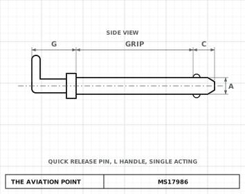
Current standard: NASM17986. MS17986 is now controlled by NASM17986 (MS17986G, Notice 1). The part numbers do not change: MS17986C303 is still the number on drawings, IPCs and bags, and it is the same part. Order it by that number; the current document is NASM17986.
Specification
| Item | Value |
|---|---|
| Current standard | NASM17986 (part numbers unchanged) |
| Type | Quick release pin, L handle |
| Material | Shank and spindle: corrosion-resistant steel 17-4PH (UNS S17400, AMS 5643) or PH15-7Mo (UNS S15700, AMS 5657), heat treated per MIL-H-6875 to condition H-900 (17-4PH) or CH-900 (PH15-7Mo), Rockwell C40 min; locking elements: CRES 440C (UNS S44004, AMS 5630 or AMS 5880); handle and button: CRES 303 (ASTM A484, A581 or A582) or aluminum alloy 380 (QQ-A-591), 2011 (QQ-A-225/3), 2017 (QQ-A-225/5), 2024 (QQ-A-225/6) or 6061-T6 (QQ-A-200/8 or QQ-A-225/8); collar: CRES 301, 302, 303 or 304; spring: CRES 17-7PH (AMS 5678) or CRES 302 Class 1 (ASTM A313); attaching link or ring: CRES 17-7PH, spring temper (AMS 5678), or CRES 302 (ASTM A313) |
| Finish | CRES parts passivated (QQ-P-35); aluminum alloy parts anodized (MIL-A-8625, Type I or II, Class 2) or chemical film (MIL-C-5541, Class 1A); handles black |
| Status | Check the current issue before design use. Cancelled by Notice 1 (Nov 1998) and superseded by NASM17986; the notice states the part numbers are identical. |
Dimensions by size
| Dimension, in | 3/16 | 1/4 | 5/16 | 3/8 | 7/16 | 1/2 | 9/16 | 5/8 | 3/4 | 7/8 | 1 |
|---|---|---|---|---|---|---|---|---|---|---|---|
| A max — A dia, max | .1885 | .2485 | .3110 | .3735 | .4360 | .4985 | .5610 | .6235 | .7485 | .8735 | .9985 |
| A min — A dia, min | .1870 | .2470 | .3095 | .3720 | .4345 | .4970 | .5595 | .6220 | .7470 | .8720 | .9970 |
| B — B, ±.005 | .220 | .289 | .375 | .440 | .509 | .594 | .666 | .750 | .887 | 1.045 | 1.219 |
| C — C, +.000 −.040 | .260 | .290 | .330 | .365 | .380 | .460 | .510 | .580 | .670 | .760 | .890 |
| D max — D dia, max | .310 | .310 | .310 | .390 | .390 | .565 | .565 | .580 | .700 | .840 | .950 |
| D min — D dia, min | .250 | .250 | .250 | .300 | .300 | .435 | .435 | .450 | .570 | .700 | .750 |
| E max — E dia, max | .500 | .500 | .500 | .625 | .625 | .800 | .800 | .975 | 1.000 | 1.320 | 1.320 |
| E min — E dia, min | .380 | .380 | .380 | .510 | .510 | .630 | .630 | .810 | .810 | 1.120 | 1.180 |
| F max — F, max | 1.800 | 1.800 | 1.800 | 2.030 | 2.030 | 2.360 | 2.360 | 3.070 | 3.070 | 3.700 | 3.700 |
| F min — F, min | 1.720 | 1.720 | 1.720 | 1.945 | 1.945 | 2.230 | 2.230 | 2.385 | 2.465 | 2.750 | 2.750 |
| G — G, max | 1.270 | 1.270 | 1.270 | 1.450 | 1.470 | 1.600 | 1.600 | 1.700 | 1.720 | 2.170 | 2.170 |
| H — H, min | .760 | .760 | .760 | .850 | .850 | .850 | .850 | .905 | .980 | 1.200 | 1.200 |
| K — K, max | .340 | .340 | .340 | .390 | .390 | .500 | .500 | .600 | .600 | .800 | .800 |
| Double shear, min, lb | 5150 | 9200 | 14400 | 20600 | 28000 | 36800 | 46000 | 57500 | 82500 | 112500 | 147000 |
| Tensile strength, min, lb | 200 | 230 | 510 | 575 | 710 | 1160 | 1420 | 2070 | 2950 | 3900 | 5480 |
| Recommended hole dia, max | .194 | .254 | .3165 | .379 | .4425 | .505 | .5675 | .630 | .757 | .882 | 1.010 |
| Recommended hole dia, min | .190 | .250 | .3125 | .375 | .4375 | .500 | .5525 | .625 | .750 | .875 | 1.000 |
Dimensions in inches, as tabulated in the standard (letters as on its drawing). Loads in pounds.
Part numbers
Every part number by nominal diameter and grip. The standard governs.
3/1697 part numbers
1/497 part numbers
5/1697 part numbers
3/895 part numbers
7/1695 part numbers
1/293 part numbers
9/1693 part numbers
5/891 part numbers
3/491 part numbers
7/890 part numbers
190 part numbers
Part number
What each code means
| Part | Meaning |
|---|---|
| Example | MS17986C410 — Corrosion-resistant steel pin, 1/4 shank diameter, grip 1.000 |
Notes from the standard
- Part number: basic MS number, C (corrosion-resistant steel pin), shank diameter in sixteenths of an inch and grip in tenths of an inch: MS17986C410 is the 1/4 pin with a 1.000 grip.
- Grip lengths from the first listed to 9.900 in steps of .100 for every diameter.
- Grip +.020 −.000, measured to the edge of the locking element hole prior to staking.
- For cost purposes 1/4, 1/2 and 5/8 pins are preferred over 3/16, 7/16 and 9/16 pins respectively.
- Collar mandatory on pins with aluminum alloy handles, optional on pins with CRES handles.
- Alloy steel pins were eliminated: numbers of Revision F with a dash in place of C (alloy steel) are cancelled and superseded in Revision G by the same number with C (MS17986-410 is superseded by MS17986C410).
Where to buy
AmericaDistributor coming soonOur partner for this region is on its way
EuropeDistributor coming soonOur partner for this region is on its way
OceaniaDistributor coming soonOur partner for this region is on its way
Distributors coming soon.
Keep going
Calculators
Guides
Data sheets
Books
Sources
- MS17986 Rev. G, 1 Jun 1994 — Pin, Quick Release, Self-Retaining, Positive Locking, Single Acting, "L" Handle — dimensions, part numbers and notes. Public domain, distribution unlimited.
Educational reference only. not approved data. Always consult the applicable SRM, AMM, or AC 43.13-1B and your certifying authority.