MS122076 at a glance
Where to buy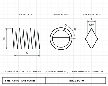
Current standard: NASM122076. MS122076 is now controlled by NASM122076 (MS122076 thru MS122115 Rev. D Notice 1). The part numbers do not change: MS122095 is still the number on drawings, IPCs and bags, and it is the same part. Order it by that number; the current document is NASM122076.
Specification
| Item | Value |
|---|---|
| Current standard | NASM122076 (part numbers unchanged) |
| Type | Helical coil insert, coarse thread |
| Material | Corrosion-resistant steel, AMS 7245 (material and manufacture) |
| Procurement | MIL-I-8846 |
| Item | Value |
|---|---|
| Status | Check the current issue before design use. Cancelled by Notice 1 (May 2000) and superseded by NASM122076 thru NASM122115; the part numbers are unchanged. |
| Supersedes | MS21208 (in part) |
| Federal supply class | 5340 |
Dimensions by size
| Dimension | .086-56 | .099-48 | .112-40 | .125-40 | .138-32 | .164-32 | .190-24 | .250-20 | .3125-18 | .375-16 | .4375-14 | .500-13 | .5625-12 | .625-11 | .750-10 | .875-9 | 1.000-8 | 1.125-7 | 1.250-7 | 1.375-6 | 1.500-6 |
|---|---|---|---|---|---|---|---|---|---|---|---|---|---|---|---|---|---|---|---|---|---|
| A min — A, min flat (view AB) | .0027 | .0043 | .0068 | .0068 | .0076 | .0076 | .0120 | .0164 | .0176 | .0215 | .0267 | .0273 | .0334 | .0351 | .0402 | .0466 | .0544 | .0645 | .0645 | .0775 | .0775 |
| B min — B, min (free outer dia) | .110 | .128 | .144 | .158 | .178 | .205 | .244 | .310 | .380 | .452 | .526 | .597 | .669 | .742 | .881 | 1.022 | 1.166 | 1.315 | 1.443 | 1.598 | 1.727 |
| B max — B, max (free outer dia) | .119 | .139 | .159 | .173 | .193 | .220 | .259 | .330 | .400 | .472 | .551 | .622 | .694 | .767 | .906 | 1.052 | 1.196 | 1.355 | 1.483 | 1.643 | 1.772 |
| C — C, number of free coils (±.250 coil) | 3.000 | 2.875 | 2.750 | 3.250 | 2.750 | 3.500 | 2.875 | 3.375 | 4.000 | 4.375 | 4.500 | 4.875 | 5.125 | 5.250 | 5.875 | 6.250 | 6.375 | 6.125 | 7.000 | 6.500 | 7.250 |
| D min — D, min (section X-X) | .0163 | .0196 | .0241 | .0241 | .0295 | .0295 | .0410 | .0500 | .0560 | .0636 | .0730 | .0758 | .0861 | .0909 | .1007 | .1124 | .1264 | .1451 | .1451 | .1695 | .1695 |
| D max — D, max (section X-X) | .0193 | .0226 | .0271 | .0271 | .0338 | .0338 | .0449 | .0540 | .0600 | .0677 | .0770 | .0829 | .0900 | .0980 | .1079 | .1199 | .1350 | .1546 | .1546 | .1799 | .1799 |
| E min — E, min (section X-X) | .0126 | .0152 | .0189 | .0189 | .0233 | .0233 | .0305 | .0378 | .0416 | .0477 | .0545 | .0593 | .0649 | .0715 | .0795 | .0892 | .1004 | .1160 | .1160 | .1368 | .1368 |
| E max — E, max (section X-X) | .0156 | .0182 | .0219 | .0219 | .0273 | .0273 | .0365 | .0438 | .0486 | .0547 | .0625 | .0673 | .0729 | .0795 | .0875 | .0972 | .1094 | .1250 | .1250 | .1458 | .1458 |
| F — F, gage (section X-X) | .00893 | .01042 | .01250 | .01250 | .01563 | .01563 | .02083 | .02500 | .02778 | .03125 | .03571 | .03846 | .04167 | .04545 | .05000 | .05556 | .06250 | .07143 | .07143 | .08333 | .08333 |
| H min — H, min (section X-X) | .0112 | .01313 | .01584 | .01584 | .01985 | .01985 | .02656 | .03198 | .03558 | .04009 | .04589 | .04946 | .05363 | .05855 | .06445 | .07167 | .08069 | .09229 | .09229 | .10775 | .10775 |
| H max — H, max (section X-X) | .0116 | .01353 | .01624 | .01624 | .02030 | .02030 | .02706 | .03248 | .03608 | .04059 | .04639 | .04996 | .05413 | .05905 | .06495 | .07217 | .08119 | .09279 | .09279 | .10825 | .10825 |
| J min — J, min (measured 30° from tang) | .103 | .120 | — | — | — | — | — | — | .375 | .445 | .518 | .586 | .656 | .727 | .840 | .991 | 1.135 | 1.260 | 1.366 | 1.545 | 1.676 |
| J max — J, max (measured 30° from tang) | .111 | .131 | — | — | — | — | — | — | .390 | .462 | .536 | .606 | .676 | .747 | .885 | 1.026 | 1.170 | 1.315 | 1.416 | 1.598 | 1.727 |
| P min — P, min | .062 | .070 | .070 | .078 | .091 | .118 | .141 | .182 | .214 | .269 | .313 | .348 | .390 | .421 | .453 | .500 | .526 | .557 | .679 | .689 | .811 |
| P max — P, max | .080 | .090 | .095 | .108 | .121 | .153 | .176 | .233 | .286 | .348 | .411 | .458 | .520 | .567 | .640 | .734 | .781 | .843 | .937 | 1.093 | 1.187 |
| Q — Q, angle | 75° - 150° | 75° - 150° | 25° - 100° | 25° - 100° | 25° - 100° | 20° - 100° | 15° - 90° | 20° - 80° | 20° - 80° | 20° - 80° | 20° - 80° | 20° - 80° | 20° - 80° | 20° - 80° | 60° - 120° | 60° - 120° | 60° - 120° | 60° - 120° | 60° - 120° | 60° - 120° | 60° - 120° |
| R min — R, min (tangent to flanks, view AB) | .0032 | .0038 | .0045 | .0045 | .0056 | .0056 | .0075 | .0090 | .0100 | .0113 | .0129 | .0139 | .0150 | .0164 | .0180 | .0200 | .0226 | .0258 | .0258 | .0301 | .0301 |
| S min — S, min (view AB) | .0056 | .0065 | .0078 | .0078 | .0098 | .0098 | .0130 | .0156 | .0174 | .0195 | .0223 | .0240 | .0260 | .0284 | .0312 | .0347 | .0391 | .0446 | .0446 | .0521 | .0521 |
Dimensions in inches, as tabulated in the standard; C is a number of coils and Q an angle. Letters as on the standard's drawing.
Part numbers
| Part no. | Size | Type | Nominal length, in | Approx. weight, lb per 100 |
|---|---|---|---|---|
| MS122095 | .086-56 | Notched | .086 | .0051 |
| MS122115 | .099-48 | Notched | .099 | .0077 |
| MS122076 | .112-40 | Notched | .112 | .0121 |
| MS122096 | .112-40 | Unnotched (inactive for design) | .112 | .0121 |
| MS122077 | .125-40 | Notched | .125 | .0154 |
| MS122097 | .125-40 | Unnotched (inactive for design) | .125 | .0154 |
| MS122078 | .138-32 | Notched | .138 | .0243 |
| MS122098 | .138-32 | Unnotched (inactive for design) | .138 | .0243 |
| MS122079 | .164-32 | Notched | .164 | .0355 |
| MS122099 | .164-32 | Unnotched (inactive for design) | .164 | .0355 |
| MS122080 | .190-24 | Notched | .190 | .0573 |
| MS122100 | .190-24 | Unnotched (inactive for design) | .190 | .0573 |
| MS122081 | .250-20 | Notched | .250 | .145 |
| MS122101 | .250-20 | Unnotched (inactive for design) | .250 | .145 |
| MS122082 | .3125-18 | Notched | .312 | .232 |
| MS122102 | .3125-18 | Unnotched (inactive for design) | .312 | .232 |
| MS122083 | .375-16 | Notched | .375 | .391 |
| MS122103 | .375-16 | Unnotched (inactive for design) | .375 | .391 |
| MS122084 | .4375-14 | Notched | .438 | .667 |
| MS122104 | .4375-14 | Unnotched (inactive for design) | .438 | .667 |
| Part no. | Size | Type | Nominal length, in | Approx. weight, lb per 100 |
|---|---|---|---|---|
| MS122085 | .500-13 | Notched | .500 | .794 |
| MS122105 | .500-13 | Unnotched (inactive for design) | .500 | .794 |
| MS122086 | .5625-12 | Notched | .562 | 1.235 |
| MS122106 | .5625-12 | Unnotched (inactive for design) | .562 | 1.235 |
| MS122087 | .625-11 | Notched | .625 | 1.515 |
| MS122107 | .625-11 | Unnotched (inactive for design) | .625 | 1.515 |
| MS122088 | .750-10 | Notched | .750 | 2.778 |
| MS122108 | .750-10 | Unnotched (inactive for design) | .750 | 2.778 |
| MS122089 | .875-9 | Notched | .875 | 4.545 |
| MS122109 | .875-9 | Unnotched (inactive for design) | .875 | 4.545 |
| MS122090 | 1.000-8 | Notched | 1.000 | 5.882 |
| MS122110 | 1.000-8 | Unnotched (inactive for design) | 1.000 | 5.882 |
| MS122091 | 1.125-7 | Notched | 1.125 | 8.392 |
| MS122111 | 1.125-7 | Unnotched (inactive for design) | 1.125 | 8.392 |
| MS122092 | 1.250-7 | Notched | 1.250 | 10.487 |
| MS122112 | 1.250-7 | Unnotched (inactive for design) | 1.250 | 10.487 |
| MS122093 | 1.375-6 | Notched | 1.375 | 14.505 |
| MS122113 | 1.375-6 | Unnotched (inactive for design) | 1.375 | 14.505 |
| MS122094 | 1.500-6 | Notched | 1.500 | 17.563 |
| MS122114 | 1.500-6 | Unnotched (inactive for design) | 1.500 | 17.563 |
Every part number of MS122076 thru MS122115, notched and unnotched, by thread size. The standard governs.
Part number
What each code means
| Part | Meaning |
|---|---|
| Example | MS122076 — Notched insert for a .112-40 thread, nominal length .112 |
Notes from the standard
- Nominal length equals the basic thickness of plate for the insert assembly. The assembled length of the insert is as specified on MS33537.
- The number of free coils is counted, and the assembled length measured, 90° from the tang.
- An insert assembled in a tapped hole as specified in MS33537 produces a finished thread meeting all requirements of MIL-S-7742 and accepts external MIL-S-8879 threads.
- Ends of coil may be square or angular. The centerline of the wire section is square with the coil axis within 5°. The first coil diameter meets the free diameter 210° from the tang, within 20°. The notch is on the top face or edge of the first coil.
- Unnotched inserts are inactive for design after 15 Oct 1969: use notched inserts. Notched inserts can universally replace the unnotched inserts, but unnotched inserts cannot replace the notched inserts.
- Surface texture per ANSI B46.1-1962. Identification: part number and manufacturer's identification marked on the container. Do not use unassigned part numbers.
Where to buy
AmericaDistributor coming soonOur partner for this region is on its way
EuropeDistributor coming soonOur partner for this region is on its way
OceaniaDistributor coming soonOur partner for this region is on its way
Distributors coming soon.
Keep going
Calculators
Data sheets
Books
Buy
Distributors coming soon.
Sources
- MS122076 thru MS122115 Rev. D, 24 Feb 1976 — Insert, CRES Helical Coil Coarse Thread, 1 Dia Nominal Length — dimensions, part numbers and notes. Public domain, distribution unlimited. Notices: Notice 1 (May 2000): MS122076 thru MS122115 Rev. D cancelled and superseded by NASM122076 thru NASM122115; the part identification numbers and the part numbers are identical.
Educational reference only. not approved data. Always consult the applicable SRM, AMM, or AC 43.13-1B and your certifying authority.