MS35190 at a glance
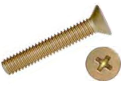
Specification
| Item | Value |
|---|---|
| Head | flat countersunk, 82 degree |
| Drive | cross-recess (MS9006) |
| Thread series | coarse (UNC-2A) |
| Material | Carbon steel per Fed. Std. No. 66, minimum ultimate tensile strength 60,000 psi. |
| Heat treatment | Tensile load based on 60,000 psi minimum ultimate tensile strength. |
| Item | Value |
|---|---|
| Finish | Cadmium plate QQ-P-416 Type II Class 3, or MIL-C-81562. |
| Procurement | FF-S-92 |
| Thread specification | Handbook H28 |
| Status | Rev. F (28 Jul 1976). Notice 1 (27 Oct 1999): canceled and superseded by NASM35190; the part numbers are identical (MS35190-209 = NASM35190-209). Approved 25 Jun 1953. |
Dimensions by size
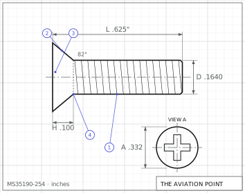
| Dimension, in | .073-64 UNC-2A | .086-56 UNC-2A | .112-40 UNC-2A | .138-32 UNC-2A | .164-32 UNC-2A | .190-24 UNC-2A | .250-20 UNC-2A | .3125-18 UNC-2A | .375-16 UNC-2A | .4375-14 UNC-2A | .500-13 UNC-2A |
|---|---|---|---|---|---|---|---|---|---|---|---|
| nominal | #1 | #2 | #4 | #6 | #8 | #10 | 1/4 | 5/16 | 3/8 | 7/16 | 1/2 |
| D body dia | .0603 – .0730 | .0717 – .0860 | .0925 – .1120 | .1141 – .1380 | .1399 – .1640 | .1586 – .1900 | .2127 – .2500 | .2712 – .3125 | .3287 – .3750 | .3850 – .4375 | .4435 – .5000 |
| A head dia | max sharp .146, min sharp .130, abs min .123 | max sharp .172, min sharp .156, abs min .147 | max sharp .225, min sharp .207, abs min .195 | max sharp .279, min sharp .257, abs min .244 | max sharp .332, min sharp .308, abs min .292 | max sharp .385, min sharp .359, abs min .340 | max sharp .507, min sharp .477, abs min .452 | max sharp .635, min sharp .600, abs min .568 | max sharp .762, min sharp .722, abs min .685 | max sharp .812, min sharp .767, abs min .723 | max sharp .875, min sharp .831, abs min .775 |
| H head height ref | .043 | .051 | .067 | .083 | .100 | .116 | .153 | .191 | .230 | .223 | .223 |
| H1 head height undercut | .023 – .031 | .028 – .036 | .038 – .047 | .048 – .059 | .058 – .070 | .068 – .081 | .092 – .107 | .116 – .134 | .140 – .161 | .133 – .156 | .130 – .156 |
| R radius max | .029 | .034 | .045 | .055 | .066 | .076 | .100 | .125 | .150 | .175 | .200 |
| R1 radius undercut max | .011 | .013 | .017 | .021 | .025 | .029 | .038 | .047 | .056 | .066 | .075 |
| min tensile lbf | 160 | 220 | 360 | 545 | 840 | 1050 | 1910 | 3140 | 4650 | 6380 | 8500 |
Minimum – maximum as tabulated in MS35190 Rev. F; letters as on the standard's drawing.
Part numbers and lengths
Every part number of MS35190 Rev. F, by thread size, each with its own link.
.073-64 UNC-2A8 part numbers · tolerance +0/-.031
| Part no. | Length, in |
|---|---|
| MS35190-201 | .125 |
| MS35190-202 | .188 |
| MS35190-203 | .250 |
| MS35190-204 | .312 |
| MS35190-205 | .375 |
| MS35190-206 | .438 |
| MS35190-207 | .500 |
| MS35190-208 | .625 |
.086-56 UNC-2A10 part numbers · tolerance +0/-.031
| Part no. | Length, in |
|---|---|
| MS35190-209 | .125 |
| MS35190-210 | .188 |
| MS35190-211 | .250 |
| MS35190-212 | .312 |
| MS35190-213 | .375 |
| MS35190-214 | .438 |
| MS35190-215 | .500 |
| MS35190-216 | .625 |
| MS35190-217 | .750 |
| MS35190-218 | .875 |
.112-40 UNC-2A13 part numbers
| Part no. | Length, in | Tol. |
|---|---|---|
| MS35190-219 | .125 | +0/-.031 |
| MS35190-220 | .188 | +0/-.031 |
| MS35190-221 | .250 | +0/-.031 |
| MS35190-222 | .312 | +0/-.031 |
| MS35190-223 | .375 | +0/-.031 |
| MS35190-224 | .438 | +0/-.031 |
| MS35190-225 | .500 | +0/-.031 |
| MS35190-226 | .625 | +0/-.031 |
| MS35190-227 | .750 | +0/-.031 |
| MS35190-228 | .875 | +0/-.031 |
| MS35190-229 | 1.000 | +0/-.031 |
| MS35190-230 | 1.250 | +0/-.062 |
| MS35190-231 | 1.500 | +0/-.062 |
.138-32 UNC-2A15 part numbers
| Part no. | Length, in | Tol. |
|---|---|---|
| MS35190-232 | .125 | +0/-.031 |
| MS35190-233 | .188 | +0/-.031 |
| MS35190-234 | .250 | +0/-.031 |
| MS35190-235 | .312 | +0/-.031 |
| MS35190-236 | .375 | +0/-.031 |
| MS35190-237 | .438 | +0/-.031 |
| MS35190-238 | .500 | +0/-.031 |
| MS35190-239 | .625 | +0/-.031 |
| MS35190-240 | .750 | +0/-.031 |
| MS35190-241 | .875 | +0/-.031 |
| MS35190-242 | 1.000 | +0/-.031 |
| MS35190-243 | 1.250 | +0/-.062 |
| MS35190-244 | 1.500 | +0/-.062 |
| MS35190-245 | 1.750 | +0/-.062 |
| MS35190-246 | 2.000 | +0/-.062 |
.164-32 UNC-2A19 part numbers
| Part no. | Length, in | Tol. |
|---|---|---|
| MS35190-247 | .125 | +0/-.031 |
| MS35190-248 | .188 | +0/-.031 |
| MS35190-249 | .250 | +0/-.031 |
| MS35190-250 | .312 | +0/-.031 |
| MS35190-251 | .375 | +0/-.031 |
| MS35190-252 | .438 | +0/-.031 |
| MS35190-253 | .500 | +0/-.031 |
| MS35190-254 | .625 | +0/-.031 |
| MS35190-255 | .750 | +0/-.031 |
| MS35190-256 | .875 | +0/-.031 |
| MS35190-257 | 1.000 | +0/-.031 |
| MS35190-258 | 1.250 | +0/-.062 |
| MS35190-259 | 1.500 | +0/-.062 |
| MS35190-260 | 1.750 | +0/-.062 |
| MS35190-261 | 2.000 | +0/-.062 |
| MS35190-262 | 2.250 | +0/-.094 |
| MS35190-263 | 2.500 | +0/-.094 |
| MS35190-264 | 2.750 | +0/-.094 |
| MS35190-265 | 3.000 | +0/-.094 |
.190-24 UNC-2A18 part numbers
| Part no. | Length, in | Tol. |
|---|---|---|
| MS35190-266 | .188 | +0/-.031 |
| MS35190-267 | .250 | +0/-.031 |
| MS35190-268 | .312 | +0/-.031 |
| MS35190-269 | .375 | +0/-.031 |
| MS35190-270 | .438 | +0/-.031 |
| MS35190-271 | .500 | +0/-.031 |
| MS35190-272 | .625 | +0/-.031 |
| MS35190-273 | .750 | +0/-.031 |
| MS35190-274 | .875 | +0/-.031 |
| MS35190-275 | 1.000 | +0/-.031 |
| MS35190-276 | 1.250 | +0/-.062 |
| MS35190-277 | 1.500 | +0/-.062 |
| MS35190-278 | 1.750 | +0/-.062 |
| MS35190-279 | 2.000 | +0/-.062 |
| MS35190-280 | 2.250 | +0/-.094 |
| MS35190-281 | 2.500 | +0/-.094 |
| MS35190-282 | 2.750 | +0/-.094 |
| MS35190-283 | 3.000 | +0/-.094 |
.250-20 UNC-2A16 part numbers
| Part no. | Length, in | Tol. |
|---|---|---|
| MS35190-284 | .312 | +0/-.031 |
| MS35190-285 | .375 | +0/-.031 |
| MS35190-286 | .438 | +0/-.031 |
| MS35190-287 | .500 | +0/-.031 |
| MS35190-288 | .625 | +0/-.031 |
| MS35190-289 | .750 | +0/-.031 |
| MS35190-290 | .875 | +0/-.031 |
| MS35190-291 | 1.000 | +0/-.031 |
| MS35190-292 | 1.250 | +0/-.062 |
| MS35190-293 | 1.500 | +0/-.062 |
| MS35190-294 | 1.750 | +0/-.062 |
| MS35190-295 | 2.000 | +0/-.062 |
| MS35190-296 | 2.250 | +0/-.094 |
| MS35190-297 | 2.500 | +0/-.094 |
| MS35190-298 | 2.750 | +0/-.094 |
| MS35190-299 | 3.000 | +0/-.094 |
.3125-18 UNC-2A15 part numbers
| Part no. | Length, in | Tol. |
|---|---|---|
| MS35190-300 | .375 | +0/-.031 |
| MS35190-301 | .438 | +0/-.031 |
| MS35190-302 | .500 | +0/-.031 |
| MS35190-303 | .625 | +0/-.031 |
| MS35190-304 | .750 | +0/-.031 |
| MS35190-305 | .875 | +0/-.031 |
| MS35190-306 | 1.000 | +0/-.031 |
| MS35190-307 | 1.250 | +0/-.062 |
| MS35190-308 | 1.500 | +0/-.062 |
| MS35190-309 | 1.750 | +0/-.062 |
| MS35190-310 | 2.000 | +0/-.062 |
| MS35190-311 | 2.250 | +0/-.094 |
| MS35190-312 | 2.500 | +0/-.094 |
| MS35190-313 | 2.750 | +0/-.094 |
| MS35190-314 | 3.000 | +0/-.094 |
.375-16 UNC-2A13 part numbers
| Part no. | Length, in | Tol. |
|---|---|---|
| MS35190-315 | .500 | +0/-.031 |
| MS35190-316 | .625 | +0/-.031 |
| MS35190-317 | .750 | +0/-.031 |
| MS35190-318 | .875 | +0/-.031 |
| MS35190-319 | 1.000 | +0/-.031 |
| MS35190-320 | 1.250 | +0/-.062 |
| MS35190-321 | 1.500 | +0/-.062 |
| MS35190-322 | 1.750 | +0/-.062 |
| MS35190-323 | 2.000 | +0/-.062 |
| MS35190-324 | 2.250 | +0/-.094 |
| MS35190-325 | 2.500 | +0/-.094 |
| MS35190-326 | 2.750 | +0/-.094 |
| MS35190-327 | 3.000 | +0/-.094 |
.4375-14 UNC-2A12 part numbers
| Part no. | Length, in | Tol. |
|---|---|---|
| MS35190-328 | .625 | +0/-.031 |
| MS35190-329 | .750 | +0/-.031 |
| MS35190-330 | .875 | +0/-.031 |
| MS35190-331 | 1.000 | +0/-.031 |
| MS35190-332 | 1.250 | +0/-.062 |
| MS35190-333 | 1.500 | +0/-.062 |
| MS35190-334 | 1.750 | +0/-.062 |
| MS35190-335 | 2.000 | +0/-.062 |
| MS35190-336 | 2.250 | +0/-.094 |
| MS35190-337 | 2.500 | +0/-.094 |
| MS35190-338 | 2.750 | +0/-.094 |
| MS35190-339 | 3.000 | +0/-.094 |
.500-13 UNC-2A11 part numbers
| Part no. | Length, in | Tol. |
|---|---|---|
| MS35190-340 | .750 | +0/-.031 |
| MS35190-341 | .875 | +0/-.031 |
| MS35190-342 | 1.000 | +0/-.031 |
| MS35190-343 | 1.250 | +0/-.062 |
| MS35190-344 | 1.500 | +0/-.062 |
| MS35190-345 | 1.750 | +0/-.062 |
| MS35190-346 | 2.000 | +0/-.062 |
| MS35190-347 | 2.250 | +0/-.094 |
| MS35190-348 | 2.500 | +0/-.094 |
| MS35190-349 | 2.750 | +0/-.094 |
| MS35190-350 | 3.000 | +0/-.094 |
Part number

What each code means
| Part | Meaning |
|---|---|
| Format | MS35190-<dash number>[L] |
| Example | MS35190-209 = plain screw, .086-56 UNC-2A, .125 long; MS35190-209L = same with self-locking element (the suffix glyph prints as a digit in this scan; read as L by comparison with MS35191) |
| Length tolerance, .125 to 1.000 | +0/-.031 |
| Length tolerance, 1.250 to 2.000 | +0/-.062 |
| Length tolerance, 2.250 to 3.000 | +0/-.094 |
| (none) | Locking: plain screw |
| L | Locking: self-locking screw (patch or strip locking element per MIL-F-18240) |
| Dash | Dash number from Table I selects thread size and length (201 to 350) |
Notes from the standard
- Head angle 82 degrees. Recess per MS9006. Screws above the dotted staircase lines of Table I (short lengths) have undercut heads (H1 / R1 dimensions); the dotted line is not legible enough in the scan to assign it dash by dash, so no per-row undercut flag is published.
- Thread class 2A, Screw-Thread Standards for Federal Services (Handbook H28). Screws 2.00 inches long and shorter have complete threads extending to within two threads of the head, or closer if practicable; longer screws have a minimum thread length of 1.50 inches.
- Self-locking screws: the locking element is a patch or longitudinal strip per MIL-F-18240; the maximum ring gage diameter that the locking region must pass freely or with finger pressure is the nominal size plus a small allowance (value not clearly legible in the scan); "X" and "Y" dimensions and design/usage limitations per MS15981.
- Dash numbers marked * in Table I are inactive for new design after 2 February 1976. Dimensions in inches.
- Sheet 2 (Table II) cross-references the AN505 / AN510 dash numbers cancelled after 24 Feb 1953 / 5 Apr 1962 (not transcribed).
- The date after which dash numbers marked * are inactive is partly illegible in this scan; read as 2 February 1976 by comparison with MS35191 and the revision block (E, 2 Feb 76).
- Head height H prints .223 for both 7/16 and 1/2 sizes (copied as printed).
Sources
- MS35190 Rev. F, 28 Jul 1976 — Screw, Machine - 82 Flat Countersunk Head, Cross-Recessed, Carbon Steel, Cadmium Plated, UNC-2A — dimensions, part numbers and notes. Public domain, distribution unlimited. Notices: 1 27 Oct 1999 Canceled and superseded by NASM35190. The Part Identification Number for MS35190F and the part number for NASM35190 are identical.
Educational reference only. not approved data. Always consult the applicable SRM, AMM, or AC 43.13-1B and your certifying authority.