The Aviation PointTechnical data sheet · theaviationpoint.com/parts/screws/ms21318/
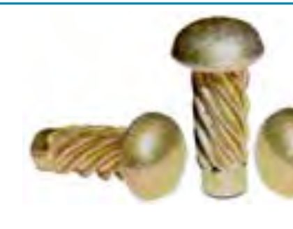
MS21318 screw — round head (dome)
Screw, Drive, Round Head, Type U, Steel, Carbon, Cadmium Plated, from MS21318 Rev. A. Every row below is transcribed from the standard and has its own link.
MS21318 at a glance
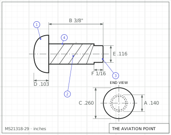
MS21318Engineering drawing · dimensions in inches
Specification
Item
Value
Head
round head (dome)
Drive
none (hammer-driven; blunt pilot end)
Thread series
Type U drive screw: multiple-start helical thread, helix angle 45 to 65 degrees (no thread class)
Material
Steel in accordance with the procurement specification (FF-S-107).
Item
Value
Finish
Cadmium plated in accordance with the procurement specification.
Procurement
FF-S-107
Status
Rev. A (13 Oct 1965; sheets marked revised A, approved 12 Aug 1959). Notice 1 (24 Jun 1994): reviewed and determined valid for use in acquisition. Notice 2 (25 Nov 1998): canceled and superseded by NASM21318; the part numbers are identical (MS21318-1 = NASM21318-1). Supersedes AN535 (see interchangeability) and two further designations whose numbers are illegible in the scan.
Dimensions by size
Dimension, in
None
None
None
None
None
None
None
None
None
None
nominal
#00
#0
#2
#4
#6
#7
#8
#10
#12
#14
threads in circumference
6
6
8
7
7
8
8
8
—
—
A body dia
.057 – .060
.072 – .075
.097 – .100
.112 – .116
.136 – .140
.150 – .154
.162 – .167
.177 – —
.206 – .212
.236 – .243
C head dia
.090 – .099
.118 – .127
.146 – .162
.193 – .211
.240 – .260
.264 – .285
.297 – —
.334 – .359
.382 – .408
.429 – .457
D head height
.026 – .034
.041 – .049
.059 – .069
.075 – .086
.091 – .103
.099 – .111
.107 – .120
.123 – .137
.139 – .153
.155 – .170
E pilot dia
.046 – .049
.060 – .063
.080 – .083
.092 – .096
.112 – .116
.122 – .126
.132 – .136
.146 – .150
.173 – .177
.198 – .202
recommended hole size
.052
.067
.086
.104
.120
.136
.144
.161
.191
.221
drill size
55
51
44
37
31
29
27
20
11
2
Minimum – maximum as tabulated in MS21318 Rev. A; letters as on the standard's drawing.
Part numbers and lengths
Every part number of MS21318 Rev. A, by thread size, each with its own link.
MS21318-1 = #00 (.058), 1/8 long (printed example); MS21318-29 = #6 (.138), 3/8 long
Length tolerance, 1/8 to 3/8
+/-1/64
Length tolerance, 1/2 to 3/4
+/-1/32
Dash
Dash number selects screw size and length (33 numbers in 10 sizes; gaps are not assigned)
Notes from the standard
Recommended use: these drive screws are not recommended for use in material whose thickness is less than one diameter of the screw.
The blunt end of the pilot may have a slight angle due to the natural flow of material in the cut-off process (note 4).
Metallic drive screws shall have fully formed threads from the base of the pilot to the head, except that threads at the starting end and under the head may be incomplete for a length equal to one-half of the maximum screw diameter (note 5).
Symbols changed to agree with ASA B18.6.4 (note 3). For design-feature purposes this standard takes precedence over the procurement documents referenced herein; referenced documents are of the issue in effect on the date of the invitation for bid.
Dimensions in inches. F is the pilot reference length per screw length (3/64 for 1/8 to 5/16, 1/16 for 3/8 and 1/2, 5/64 for 5/8 and 3/4); table cells for A, C, D, E, recommended hole and drill size are the values printed for each nominal size.
Table II (interchangeability): AN535 screws are canceled after the dates on those documents; replace them per the table (AN535-<size>-<length in 1/16> becomes the MS21318 dash shown); canceled screws may be used until stock is depleted.
Poor-quality scan. Not published (null): threads in circumference of #12 and #14; A max of #10; C max of #8. Dash lengths for #8 to #14 follow the interchangeability table; lengths of #7 (35-37) are assigned by row position. Threads in circumference of #7, #8, #10 read as 8 (glyph rendered like an S).
MS21318 Rev. A, 13 Oct 1965 — Screw, Drive, Round Head, Type U, Steel, Carbon, Cadmium Plated — dimensions, part numbers and notes. Public domain, distribution unlimited. Notices: 1 24 Jun 1994 MS21318A has been reviewed and determined to be valid for use in acquisition.; 2 25 Nov 1998 MS21318A is canceled and superseded by NASM21318. The Part Identification Numbers for MS21318A and the part numbers for NASM21318 are identical.
Educational reference only. not approved data. Always consult the applicable SRM, AMM, or AC 43.13-1B and your certifying authority.