The Aviation PointTechnical data sheet · theaviationpoint.com/parts/screws/ms24678/
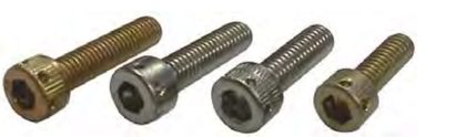
MS24678 screw — cylindrical socket head cap, drilled for safety wire (plain or knurled)
Screw, Cap, Socket Head, Hexagon, Drilled Alloy Steel, UNF-3A, from MS24678 Rev. E. Every row below is transcribed from the standard and has its own link.
MS24678 at a glance
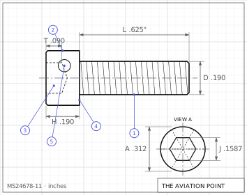
MS24678Engineering drawing · dimensions in inches
Specification
Item
Value
Head
cylindrical socket head cap, drilled for safety wire (plain or knurled)
Drive
hexagon socket
Thread series
fine (UNF-3A)
Material
Alloy steel in accordance with the procurement specification.
Heat treatment
Hardness per the procurement specification. Tensile loads based on 180,000 psi minimum ultimate tensile strength for sizes up to #10 (.190) and 170,000 psi for sizes over #10, load pounds from the stress areas of FED-STD-H28/2.
Item
Value
Finish
Uncoated; cadmium plate QQ-P-416 Type II Class 3 (do not use cadmium plated screws above 450 F); or aluminum ion vapor deposited coating MIL-C-83488 Type II Class 3 (usable to 850 F).
Procurement
FF-S-86
Thread specification
FED-STD-H28/2
Status
Rev. E (2 Jan 1992). Notice 1 (25 Nov 1998): canceled and superseded by NASM24678; the part numbers are identical (MS24678-1 = NASM24678-1). Supersedes MS24678D (5 Mar 1986) and MS24675 (canceled 7 Jul 1975; MS24675-1 to -70 became MS24678-1 to -70).
Dimensions by size
Dimension, in
.138-40 UNF-3A
.164-36 UNF-3A
.190-32 UNF-3A
.250-28 UNF-3A
.3125-24 UNF-3A
.375-24 UNF-3A
.4375-20 UNF-3A
.500-20 UNF-3A
.625-18 UNF-3A
nominal
#6
#8
#10
1/4
5/16
3/8
7/16
1/2
5/8
D body dia
.1329 – .1380
.1585 – .1640
.1840 – .1900
.2435 – .2500
.3053 – .3125
.3678 – .3750
.4294 – .4375
.4919 – .5000
.6163 – .6250
A head dia
.218 – .226
.262 – .270
.303 – .312
.365 – .375
.457 – .469
.550 – .562
.642 – .656
.735 – .750
.921 – .938
H head height
.134 – .138
.159 – .164
.185 – .190
.244 – .250
.306 – .312
.368 – .375
.430 – .438
.492 – .500
.616 – .625
S head side height min
.124
.148
.171
.225
.281
.337
.394
.450
.562
J socket across flats
.1094 – .1111
.1406 – .1426
.1562 – .1587
.1875 – .1900
.2500 – .2530
.3125 – .3160
.3750 – .3790
.3750 – .3790
.5000 – .5050
T key engagement min
.064
.077
.090
.120
.151
.182
.213
.245
.307
G wall thickness min
.047
.056
.065
.095
.119
.143
.166
.190
.238
C chamfer or radius max
.005
.005
.005
.008
.008
.008
.010
.010
.010
R fillet extension
.006 – .010
.007 – .012
.009 – .014
.009 – .014
.012 – .017
.015 – .020
.018 – .023
.020 – .026
.024 – .032
K hole location
.035 – .050
.040 – .060
.045 – .065
.065 – .085
.084 – .104
.103 – .123
.121 – .141
.140 – .160
.178 – .198
E hole dia
.033 – .039
.044 – .050
.044 – .050
.044 – .050
.044 – .050
.061 – .067
.061 – .067
.061 – .067
.061 – .067
recommended wire dia
.020 – .028
.032 – .040
.032 – .040
.032 – .040
.032 – .040
.045 – .057
.045 – .057
.045 – .057
.045 – .057
alignment plug dia
.025
.030
.030
.030
.030
.051
.051
.051
.051
min tensile lbf
1830
2650
3600
6190
9860
14900
20200
27200
43500
holes through head
1
3
3
3
3
3
3
3
3
status
—
—
—
—
—
—
inactive for new design
—
—
Minimum – maximum as tabulated in MS24678 Rev. E; letters as on the standard's drawing.
Part numbers and lengths
Every part number of MS24678 Rev. E, by thread size, each with its own link.
.138-40 UNF-3A5 part numbers · tolerance +0.00/-0.03
Dash number from Table I selects thread size and length (1 to 70)
(none)
Finish: cadmium plate
A
Finish: aluminum ion vapor deposited coating
U
Finish: no protective coating or surface treatment
Notes from the standard
Threads per FED-STD-H28/2; acceptability FED-STD-H28/20 System 22. Screws above the heavy line (threaded_to_head = true) have complete threads to within two threads of the head; rows below it carry LG max and LB min.
Head may or may not be knurled at the manufacturer's option; knurled head diameter must not exceed the maximum head diameter.
Drilled hole data: one hole through the head on #6 (.138); three holes on #8 (.164) and larger. Hole edges on the outside of the head are chamfered 45 degrees by 0.010 to 0.020 deep. Alignment plug shall pass completely through the drilled holes.
Size 7/16 (.4375, dash 53 to 56) is inactive for new design.
The printed example MS24678-1U reads ".138-40 UNC-3A" (the size is UNF-3A as in Table I).
Scanned sheet: lengths for the 5/16 to 5/8 columns (dash 30 to 70) were assigned by row position and confirmed with the printed grip pattern (7/16: dash 53 to 56 = 1.000, 1.250, 1.500, 2.000; 1/2: dash 57 to 64 = 1.000 to 2.500 and 3.000).
Interchangeability: MS24675 was canceled and superseded by MS24678 effective 7 Jul 1975 (MS24675-1 to -70 by MS24678-1 to -70, same dash numbers).