CR9163 — universal head, serrated stem, aluminium

Cherry MS-type self-plugging blind rivet, universal head, serrated stem, from CR9163 Rev. L. Every row below is transcribed from the standard and has its own link.

CR9163 at a glance

Photo to come
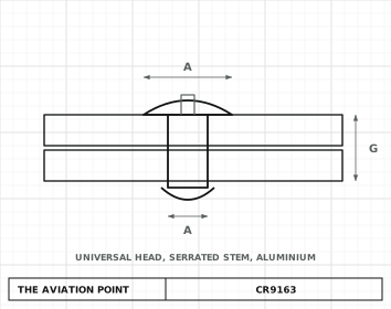
CR9163 engineering drawing with dimensions
Engineering drawing · dimensions in inches

Specification

ItemValue
TypeBlind rivet, self-plugging
MaterialSleeve: 2117 aluminium (QQ-A-430). Stem: 2017 aluminium (QQ-A-430). Material designation refers to chemical composition only.
LockingSerrated stem, self-plugging (stem breaks and plugs the sleeve)
ItemValue
FinishChemical conversion coating per MIL-DTL-5541 on sleeve and stem (code letter G: the same, to Class 1A Type II, REACH-compliant coating).
ProcurementMIL-R-7885
StatusManufacturer drawing, revision shown in the source block. Check the manufacturer for any later revision before ordering.

Dimensions by size

Dimension, in-4-5-6-8
A — A, head diameter range.262 – .238.328 – .296.394 – .356.525 – .475
B — B, nominal (tolerance +.010 / -.000).054.067.080.107
D — D, nominal sleeve diameter (tolerance +.003 / -.001).125.156.187.250
F — F, min.750.750.7501.000
H — H, max.110.138.161.215
S — S, nominal (tolerance ±.003).086.108.127.170

Maximum – minimum as tabulated in CR9163 Rev. L; letters as on the standard's drawing.

Part numbers

Every part number of CR9163 Rev. L, each with its own link. Codes (material, finish) build the full number in the box below.
-4 (.125 nominal)12 part numbers

Part no.Grip min, inGrip max, inL max, inK max, in
CR9163-4-01.025.062.170.500
CR9163-4-02.063.125.232.600
CR9163-4-03.126.187.295.750
CR9163-4-04.188.250.357.850
CR9163-4-05.251.312.4201.010
CR9163-4-06.313.375.4821.100
CR9163-4-07.376.437.5451.197
CR9163-4-08.438.500.6071.322
CR9163-4-09.501.562.6701.509
CR9163-4-10.563.625.7221.600
CR9163-4-11.626.687.7851.730
CR9163-4-12.688.750.8471.820

-5 (.156 nominal)14 part numbers

Part no.Grip min, inGrip max, inL max, inK max, in
CR9163-5-01.031.062.192.558
CR9163-5-02.063.125.254.620
CR9163-5-03.126.187.317.808
CR9163-5-04.188.250.379.870
CR9163-5-05.251.312.4411.058
CR9163-5-06.313.375.5031.120
CR9163-5-07.376.437.5671.339
CR9163-5-08.438.500.6291.401
CR9163-5-09.501.562.6921.567
CR9163-5-10.563.625.7541.630
CR9163-5-11.626.687.8171.817
CR9163-5-12.688.750.8791.880
CR9163-5-13.751.812.9422.067
CR9163-5-14.813.8751.0042.130

-6 (.187 nominal)16 part numbers

Part no.Grip min, inGrip max, inL max, inK max, in
CR9163-6-01.037.062.215.638
CR9163-6-02.063.125.277.700
CR9163-6-03.126.187.340.888
CR9163-6-04.188.250.402.950
CR9163-6-05.251.312.4651.138
CR9163-6-06.313.375.5271.200
CR9163-6-07.376.437.5901.419
CR9163-6-08.438.500.6521.481
CR9163-6-09.501.562.7151.637
CR9163-6-10.563.625.7771.699
CR9163-6-11.626.687.8401.887
CR9163-6-12.688.750.9021.949
CR9163-6-13.751.812.9652.074
CR9163-6-14.813.8751.0272.199
CR9163-6-15.876.9371.0902.330
CR9163-6-16.9381.0001.1522.450

-8 (.250 nominal)15 part numbers

Part no.Grip min, inGrip max, inL max, inK max, in
CR9163-8-02.063.125.322.850
CR9163-8-03.126.187.385.970
CR9163-8-04.188.250.4471.090
CR9163-8-05.251.312.5101.220
CR9163-8-06.313.375.5721.340
CR9163-8-07.376.437.6351.470
CR9163-8-08.438.500.6971.590
CR9163-8-09.501.562.7601.720
CR9163-8-10.563.625.8221.840
CR9163-8-11.626.687.8851.970
CR9163-8-12.688.750.9472.090
CR9163-8-13.751.8121.0102.220
CR9163-8-14.813.8751.0722.340
CR9163-8-15.876.9371.1342.405
CR9163-8-16.9381.0001.1962.530

Part number

What each code means

PartMeaning
FormatCR9163{fin}-<dash>
(none)Fin: Standard finish: chemical conversion coating per MIL-DTL-5541
PRFin: PR code: the drawing says these parts are made bare; if lubricant is needed use PAR90 only
GFin: REACH-compliant coating (chemical film Class 1A Type II)
GPRFin: REACH-compliant coating, bare / PR condition
ExampleCR9163G-8-04 — Finish code G, diameter dash -8 (1/4 in nominal sleeve diameter .250), grip dash -04 (grip range .188-.250 in)

Notes from the standard

  • Part number: basic number, optional finish letters, diameter dash, grip dash (e.g. CR9163-8-04).
  • The head diameter A is a range, not a max/min pair of a nominal value.
  • Grip ranges may also be used in a 1/64 in thicker grip. Minimum grip on the -01 grip is .025 (-4), .031 (-5) and .037 (-6); -8 has no -01.
  • Grips -02 in the -8 diameter, and -15 and -16 in the -6 diameter, are not listed on the NASM20600 drawing (see the flagged rows).
  • Sizes shown below heavy lines in the manufacturer's table are special order only; the heavy lines are not legible in our copy, so check the original.
  • Dimensions are in inches, after finish and before lubrication.

Sources

Educational reference only. not approved data. Always consult the applicable SRM, AMM, or AC 43.13-1B and your certifying authority.
esc
↑↓ navigate↵ openesc close