The Aviation PointTechnical data sheet · theaviationpoint.com/parts/screws/ms16996/
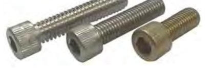
MS16996 screw — cylindrical socket head cap (knurled or plain)
Screw, Cap, Socket Head, Hexagon, Corrosion Resistant Steel, UNF-3A, from MS16996 Rev. F. Every row below is transcribed from the standard and has its own link.
MS16996 at a glance
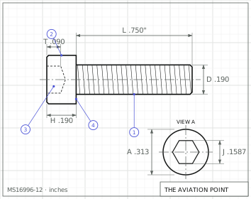
MS16996Engineering drawing · dimensions in inches
Specification
Item
Value
Head
cylindrical socket head cap (knurled or plain)
Drive
hexagon socket
Thread series
fine (UNF-3A)
Material
Corrosion resistant steel Types 302 (UNS S30200), 303 (S30300), 304 (S30400), 302HQ (S30430), 305 (S30500) and 316 (S31600), per the procurement specification.
Heat treatment
Minimum tensile strength 80,000 psi (load per Table I, from the stress areas of FED-STD-H28/2).
Item
Value
Finish
Cleaned, descaled and passivated per QQ-P-35; black oxide per MIL-C-13924 Class 4 when specified (dash number followed by code letter B).
Procurement
FF-S-86
Thread specification
FED-STD-H28/2
Status
Rev. F (24 Nov 1993). Notice 1 (30 Jun 1998): canceled and superseded by NASM16996; the part numbers are identical (MS16996-1 = NASM16996-1). Supersedes MS16996E (28 Sep 1988).
Dimensions by size
Dimension, in
.0600-80 UNF-3A
.1900-32 UNF-3A
.2500-28 UNF-3A
.3125-24 UNF-3A
.3750-24 UNF-3A
nominal
#0
#10
1/4
5/16
3/8
D body dia
.0568 – .0600
.1840 – .1900
.2435 – .2500
.3053 – .3125
.3678 – .3750
A head dia
.091 – .096
.303 – .313
.365 – .375
.457 – .469
.550 – .563
H head height
.057 – .060
.185 – .190
.244 – .250
.306 – .313
.368 – .375
S head side height min
.054
.171
.225
.281
.337
J socket across flats
.0500 – .0510
.1562 – .1587
.1875 – .1900
.2500 – .2530
.3125 – .3160
T key engagement min
.025
.090
.120
.151
.182
G wall thickness min
.020
.065
.095
.119
.143
K chamfer or radius max
.003
.005
.008
.008
.008
R fillet radius
.003 – .007
.009 – .014
.009 – .014
.015 – .017
.015 – .020
M basic thread length ref
.500
.875
1.000
1.125
1.250
min tensile lbf
140
1600
2910
4640
7020
Minimum – maximum as tabulated in MS16996 Rev. F; letters as on the standard's drawing.
Part numbers and lengths
Every part number of MS16996 Rev. F, by thread size, each with its own link.
.0600-80 UNF-3A4 part numbers · tolerance +.000/-.030
MS16996-1B = .060-80 UNF-3A, .125 long, black oxide coating
Length tolerance, .125 to 1.000
+.000/-.030
Length tolerance, 1.250 to 1.500
+.000/-.040
Dash
Dash number from Table I selects thread size and length (1 to 42, with gaps)
(none)
Finish: cleaned, descaled and passivated
B
Finish: black oxide coated
Notes from the standard
Thread: FED-STD-H28/2. Acceptability FED-STD-H28/20 System 22; for sizes .060 (#0) and .190 (#10) System 21 (as read from the scan). Screws above the heavy line (threaded_to_head = true) have complete threads to within two threads of the head.
Rows with grip_max / body_min are below the heavy line in Table I (dash 15, 16 and 26). The basic thread length M is a reference value controlled by the grip length and L.
Head of screw may be knurled or not at the manufacturer's option; type of knurling optional. Magnetic permeability 2.0 maximum (air = 1.0) at H = 200 oersteds, MIL-I-17214.
Source identification marking on screws of nominal size .250 and larger (raised or depressed, top or side of the head).
Decimal points are not printed in Table I of the scanned sheet; values are read with the leading decimal point (for example 0600 = .0600, 096 = .096, 1 125 = 1.125). The 5/16 fillet R minimum is printed .015 (read from the scan).
The .0600 size head A max .096 and #10 head A max .313 are as printed (other standards in this family show .312 for #10).
Dash numbers 5-8, 17-20, 27-30 and 35-38 are not assigned.