The Aviation PointTechnical data sheet · theaviationpoint.com/parts/screws/ms16997/
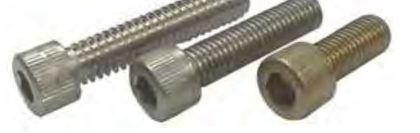
MS16997 screw — cylindrical socket head cap (plain or knurled); optional self-locking element
Screw, Cap, Socket Head and Screw, Cap, Socket Head, Self-Locking, Alloy Steel, Cadmium Plated, UNC-3A, from MS16997 Rev. D. Every row below is transcribed from the standard and has its own link.
MS16997 at a glance
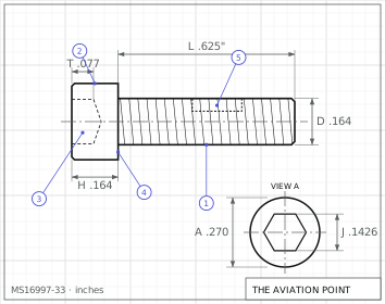
MS16997Engineering drawing · dimensions in inches
Specification
Item
Value
Head
cylindrical socket head cap (plain or knurled); optional self-locking element
Drive
hexagon socket
Thread series
coarse (UNC-3A)
Material
Alloy steel in accordance with the procurement specification.
Heat treatment
Tensile loads (Table I) based on 160,000 psi minimum ultimate tensile strength, load pounds calculated from the stress areas of Handbook H28.
Item
Value
Finish
Cadmium plating in accordance with the procurement specification.
Procurement
FF-S-86
Thread specification
FED-STD-H28/2
Status
Rev. D (31 Dec 1976). Notice 2 (24 Jul 2001; supersedes Notice 1 of 24 Jun 1994): canceled and superseded by NAS1352. Supersedes in part earlier BCW-series screws and MS35455, MS35457 and MS35459 (title block, read from the scan).
Dimensions by size
Dimension, in
.0860-56 UNC-3A
.1120-40 UNC-3A
.1380-32 UNC-3A
.1640-32 UNC-3A
.1900-24 UNC-3A
.2500-20 UNC-3A
.3125-18 UNC-3A
.3750-16 UNC-3A
.4375-14 UNC-3A
.5000-13 UNC-3A
.6250-11 UNC-3A
.7500-10 UNC-3A
.8750-9 UNC-3A
1.0000-8 UNC-3A
nominal
#2
#4
#6
#8
#10
1/4
5/16
3/8
7/16
1/2
5/8
3/4
7/8
1
D body dia
.0822 – .0860
.1075 – .1120
.1329 – .1380
.1585 – .1640
.1840 – .1900
.2435 – .2500
.3053 – .3125
— – .3750
.4294 – .4375
.4919 – .5000
.6163 – .6250
.7406 – .7500
.8647 – .8750
.9886 – 1.0000
A head dia
.134 – .140
.176 – .183
.218 – .226
.262 – .270
.303 – .3125
.365 – .375
.457 – —
.550 – .5625
.642 – .6562
.735 – .750
.921 – .9375
1.107 – 1.125
1.291 – 1.3125
1.479 – 1.500
H head height
.083 – .086
.108 – .112
.134 – .138
.159 – .164
.185 – .190
.244 – .250
.306 – .3125
— – .375
.430 – .4375
.492 – .500
.616 – .625
.740 – .750
.864 – .875
.988 – 1.000
S head side height min
.077
.101
.124
.148
.171
.225
.281
.337
.394
.450
.562
.675
.787
.900
J socket across flats
— – .0791
.0937 – .0952
.1094 – .1111
.1406 – .1426
.1562 – .1587
— – .1900
.2500 – .2530
.3125 – .3160
.3750 – .3790
.3750 – .3790
.5000 – .5050
.6250 – .6310
.7500 – .7570
.7500 – .7570
T key engagement min
.038
.051
.064
.077
.090
.120
.151
—
.213
.245
—
.370
.432
.495
G wall thickness min
.029
.038
.047
.056
.065
.095
.119
.143
.166
.190
.238
.285
.333
.380
K chamfer or radius max
.003
.005
.005
.005
.005
—
.008
—
.010
.010
.010
.010
.015
.015
F fillet extension
.004 – —
.005 – —
.006 – .010
.007 – .012
.009 – .014
.009 – .014
.012 – .017
.015 – .020
.018 – .023
.020 – .026
.024 – .032
.030 – .039
.034 – .044
.040 – .050
min tensile lbf
560
920
1400
2170
2710
4950
—
12100
16700
22300
35600
52500
73000
95500
status
—
—
—
—
—
—
—
—
inactive for new design after 31 December 1976
—
—
—
inactive for new design after 31 December 1976
—
Minimum – maximum as tabulated in MS16997 Rev. D; letters as on the standard's drawing.
Part numbers and lengths
Every part number of MS16997 Rev. D, by thread size, each with its own link.
.0860-56 UNC-3A4 part numbers · tolerance +.000/-.031
+.000/-.040 (#2 to 3/8), -.060 (7/16 to 3/4), -.100 (7/8 and 1)
Length tolerance, 2.750 to 6.000
-.060 (#2 to 1/4), -.060 (5/16, 3/8), -.080 (7/16 to 3/4), -.140 (7/8, 1)
Length tolerance, 6.500 to 8.000
+.000/-.120 (up to 3/4), -.200 (7/8 and 1)
Length tolerance, note
Page 3 (5/8 to 1): 1.000 is -.031 up to 3/4 and -.050 for 7/8 and 1; 1.250 to 2.500 -.060 / -.100; 2.750 to 6.000 -.080 / -.140; 6.500 to 8.000 -.120 / -.200. Per-row values are in each row.
Dash
Dash number from Table I selects thread size and length (1 to 242, with gaps)
(none)
Finish: plain screw (no self-locking element)
L
Finish: self-locking screw (letter L after the dash number)
Notes from the standard
Scanned sheet of low resolution: cells that cannot be read with certainty are published as null (see below); dash numbers, lengths and grip values were read at 300 dpi and checked against the printed grip pattern and the ECAS listing for the small sizes.
Thread: Unified external class 3A UNC per the procurement specification. Screws above the heavy line (threaded_to_head = true), sizes #2 to 5/8 inclusive, have complete (full form) threads to within two threads of the head, checked with a thread ring gage; larger than 5/8 have complete threads as close to the head as practicable.
Head may be knurled or not at the manufacturer's option; type of knurling optional. Hexagon socket; acceptable socket design per Figure 1 (form within 120 degrees minimum included angle at minimum material limit).
Self-locking element (suffix L): per MIL-F-18240 (patch type or longitudinal strip); for X and Y dimensions, design and usage limitations see MS15981. Maximum ring gage diameter that the locking region must pass through freely or with finger pressure is the nominal size plus 0.010.
Dash numbers 117 to 132 (7/16) and 209 to 223 (7/8) are inactive for new design after 31 December 1976 (footnote ** in the table; those columns are crossed out in the scan).
Null cells in sizes: .0860 J min, R max; .1120 R max; .2500 J min, K; .3125 A max, tensile; .3750 D min, H min, T, K; .6250 T (digit not legible; the same cells of MS16995 and MS24677 show .0781, .009, .1875, .008, .469, .368 etc., not copied).
Body length min of dash 85 and 86 (5/16, 1.125 grip) is printed .647 in the scan (the pattern of the other rows suggests .847); published as null.
Table III (sheets 5 to 7) is the metric translation of Table I (25.4 mm = 1 inch) and carries no separate part numbers; not transcribed. Sheet 4 (interchangeability with MS35455, MS35457 and MS35459) not transcribed.
Dash number 228 (1 inch, 2.000 long) is printed with a blurred first digit (read 226/228); 228 follows the sequence 228-242.