PLT111 at a glance
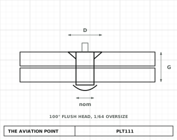
Specification
| Item | Value |
|---|---|
| Type | Blind bolt, internally threaded |
| Material | Nut and screw: alloy steel (4130 per AMS-S-6758, 4140 per AMS 6382 or AMS 6349, or 8740 per AMS 6322), heat treated per AMS 2759 to roughly 180,000-200,000 psi tensile (HRC 39-43). Sleeve: corrosion-resistant steel 303 or 304 (AMS-QQ-S-763, AMS 5639 or AMS 5641). |
| Strength | Per table: prevailing torque, double-shear and tensile strength minimums by diameter |
| Locking | Self-locking: three indents 120° apart on the nut, about .040 above where the nut nose angle meets the outside diameter (mean grip) |
| Item | Value |
|---|---|
| Finish | Nut and screw: cadmium plate per AMS-QQ-P-416 Type II Class 2 (NAS672 cadmium is acceptable if followed by a dichromate treatment). Sleeve: passivated per AMS 2700, or cadmium plate per AMS-QQ-P-416 Type I Class 3. |
| Procurement | ESCBB-2 Class I |
| Status | Manufacturer drawing, revision shown in the source block. Check the manufacturer for any later revision before ordering. |
Dimensions by size
| Dimension, in | -05 | -06 | -08 | -10 | -12 |
|---|---|---|---|---|---|
| nom — Nominal body diameter | .179 | .214 | .275 | .326 | .389 |
| D — Diameter D (screw head and sleeve must not exceed D max) | .180 – .178 | .215 – .213 | .276 – .274 | .327 – .325 | .390 – .388 |
| F — Driving flats F | .086 – .081 | .104 – .099 | .135 – .130 | .152 – .147 | .185 – .180 |
| J — Installed blind-side diameter J, max | .244 | .300 | .384 | .427 | .516 |
| K — Installed blind-side height K, max | .272 | .312 | .351 | .426 | .495 |
| C — C, max | .293 | .328 | .379 | .448 | .535 |
| H — H, ref. | .063 | .070 | .096 | .128 | .154 |
| R — R, radius | .030 – .010 | .030 – .015 | .030 – .015 | .040 – .020 | .040 – .020 |
| hole — Hole size | .183 – .180 | .218 – .215 | .279 – .276 | .330 – .327 | .393 – .390 |
| Dimension, in | -05 | -06 | -08 | -10 | -12 |
|---|---|---|---|---|---|
| breakoff — Break-off limits (upper / lower), in | +.020 – -.068 | +.015 – -.073 | +.010 – -.078 | +.010 – -.083 | +.010 – -.093 |
| torque — Prevailing torque, in-lb min | 1.0 | 1.5 | 2.5 | 3.5 | 4.0 |
| dshear — Double-shear strength, lb min | 3355 | 5240 | 9000 | 12000 | 19500 |
| tensile — Tensile strength, lb min | 900 | 1400 | 2100 | 3600 | 5600 |
| A — A, theoretical head diameter (ref.) | .332 – .325 | .385 – .378 | .507 – .499 | .635 – .626 | .762 – .752 |
| Ap — A' (A prime), head diameter min (ref.) | .296 | .342 | .463 | .577 | .696 |
| M — M, gage protrusion | .0276 – .0238 | .0299 – .0259 | .0353 – .0307 | .0409 – .0357 | .0466 – .0407 |
| S — S, max | .012 | .015 | .015 | .020 | .023 |
| W — W, gage diameter | .2671 – .2667 | .3147 – .3143 | .4245 – .4241 | .5389 – .5385 | .6532 – .6528 |
Maximum – minimum as tabulated in PLT111 Rev. R; letters as on the standard's drawing.
Part numbers
Every part number of PLT111 Rev. R, each with its own link. Codes (material, finish) build the full number in the box below.
Ø .17915 part numbers
| Part no. | G, nominal grip, in | Grip min, in | Grip max, in | L, overall screw length (ref.), in |
|---|---|---|---|---|
| PLT111-05-02 | .156 | .094 | .156 | .733 |
| PLT111-05-03 | .219 | .157 | .219 | .795 |
| PLT111-05-04 | .281 | .220 | .281 | .858 |
| PLT111-05-05 | .344 | .282 | .344 | .920 |
| PLT111-05-06 | .406 | .345 | .406 | .983 |
| PLT111-05-07 | .469 | .407 | .469 | 1.045 |
| PLT111-05-08 | .531 | .470 | .531 | 1.108 |
| PLT111-05-09 | .594 | .532 | .594 | 1.170 |
| PLT111-05-10 | .656 | .595 | .656 | 1.233 |
| PLT111-05-11 | .719 | .657 | .719 | 1.295 |
| PLT111-05-12 | .781 | .720 | .781 | 1.358 |
| PLT111-05-13 | .844 | .782 | .844 | 1.420 |
| PLT111-05-14 | .906 | .845 | .906 | 1.483 |
| PLT111-05-15 | .969 | .907 | .969 | 1.545 |
| PLT111-05-16 | 1.031 | .970 | 1.031 | 1.608 |
Ø .21431 part numbers
| Part no. | G, nominal grip, in | Grip min, in | Grip max, in | L, overall screw length (ref.), in |
|---|---|---|---|---|
| PLT111-06-02 | .156 | .094 | .156 | .853 |
| PLT111-06-03 | .219 | .157 | .219 | .916 |
| PLT111-06-04 | .281 | .220 | .281 | .978 |
| PLT111-06-05 | .344 | .282 | .344 | 1.041 |
| PLT111-06-06 | .406 | .345 | .406 | 1.103 |
| PLT111-06-07 | .469 | .407 | .469 | 1.166 |
| PLT111-06-08 | .531 | .470 | .531 | 1.228 |
| PLT111-06-09 | .594 | .532 | .594 | 1.291 |
| PLT111-06-10 | .656 | .595 | .656 | 1.353 |
| PLT111-06-11 | .719 | .657 | .719 | 1.416 |
| PLT111-06-12 | .781 | .720 | .781 | 1.478 |
| PLT111-06-13 | .844 | .782 | .844 | 1.541 |
| PLT111-06-14 | .906 | .845 | .906 | 1.603 |
| PLT111-06-15 | .969 | .907 | .969 | 1.666 |
| PLT111-06-16 | 1.031 | .970 | 1.031 | 1.728 |
| PLT111-06-17 | 1.094 | 1.032 | 1.094 | 1.791 |
| PLT111-06-18 | 1.156 | 1.095 | 1.156 | 1.853 |
| PLT111-06-19 | 1.219 | 1.157 | 1.219 | 1.916 |
| PLT111-06-20 | 1.281 | 1.220 | 1.281 | 1.978 |
| PLT111-06-21 | 1.344 | 1.282 | 1.344 | 2.041 |
| PLT111-06-22 | 1.406 | 1.345 | 1.406 | 2.103 |
| PLT111-06-23 | 1.469 | 1.407 | 1.469 | 2.166 |
| PLT111-06-24 | 1.531 | 1.470 | 1.531 | 2.228 |
| PLT111-06-25 | 1.594 | 1.532 | 1.594 | 2.291 |
| PLT111-06-26 | 1.656 | 1.595 | 1.656 | 2.353 |
| PLT111-06-27 | 1.719 | 1.657 | 1.719 | 2.416 |
| PLT111-06-28 | 1.781 | 1.720 | 1.781 | 2.478 |
| PLT111-06-29 | 1.844 | 1.782 | 1.844 | 2.541 |
| PLT111-06-30 | 1.906 | 1.845 | 1.906 | 2.603 |
| PLT111-06-31 | 1.969 | 1.907 | 1.969 | 2.666 |
| PLT111-06-32 | 2.031 | 1.970 | 2.031 | 2.728 |
Ø .27530 part numbers
| Part no. | G, nominal grip, in | Grip min, in | Grip max, in | L, overall screw length (ref.), in |
|---|---|---|---|---|
| PLT111-08-03 | .219 | .157 | .219 | .944 |
| PLT111-08-04 | .281 | .220 | .281 | 1.006 |
| PLT111-08-05 | .344 | .282 | .344 | 1.069 |
| PLT111-08-06 | .406 | .345 | .406 | 1.131 |
| PLT111-08-07 | .469 | .407 | .469 | 1.194 |
| PLT111-08-08 | .531 | .470 | .531 | 1.256 |
| PLT111-08-09 | .594 | .532 | .594 | 1.319 |
| PLT111-08-10 | .656 | .595 | .656 | 1.381 |
| PLT111-08-11 | .719 | .657 | .719 | 1.444 |
| PLT111-08-12 | .781 | .720 | .781 | 1.506 |
| PLT111-08-13 | .844 | .782 | .844 | 1.569 |
| PLT111-08-14 | .906 | .845 | .906 | 1.631 |
| PLT111-08-15 | .969 | .907 | .969 | 1.694 |
| PLT111-08-16 | 1.031 | .970 | 1.031 | 1.756 |
| PLT111-08-17 | 1.094 | 1.032 | 1.094 | 1.819 |
| PLT111-08-18 | 1.156 | 1.095 | 1.156 | 1.881 |
| PLT111-08-19 | 1.219 | 1.157 | 1.219 | 1.944 |
| PLT111-08-20 | 1.281 | 1.220 | 1.281 | 2.006 |
| PLT111-08-21 | 1.344 | 1.282 | 1.344 | 2.069 |
| PLT111-08-22 | 1.406 | 1.345 | 1.406 | 2.131 |
| PLT111-08-23 | 1.469 | 1.407 | 1.469 | 2.194 |
| PLT111-08-24 | 1.531 | 1.470 | 1.531 | 2.256 |
| PLT111-08-25 | 1.594 | 1.532 | 1.594 | 2.319 |
| PLT111-08-26 | 1.656 | 1.595 | 1.656 | 2.381 |
| PLT111-08-27 | 1.719 | 1.657 | 1.719 | 2.444 |
| PLT111-08-28 | 1.781 | 1.720 | 1.781 | 2.506 |
| PLT111-08-29 | 1.844 | 1.782 | 1.844 | 2.569 |
| PLT111-08-30 | 1.906 | 1.845 | 1.906 | 2.631 |
| PLT111-08-31 | 1.969 | 1.907 | 1.969 | 2.694 |
| PLT111-08-32 | 2.031 | 1.970 | 2.031 | 2.756 |
Ø .32629 part numbers
| Part no. | G, nominal grip, in | Grip min, in | Grip max, in | L, overall screw length (ref.), in |
|---|---|---|---|---|
| PLT111-10-04 | .281 | .220 | .281 | 1.158 |
| PLT111-10-05 | .344 | .282 | .344 | 1.221 |
| PLT111-10-06 | .406 | .345 | .406 | 1.283 |
| PLT111-10-07 | .469 | .407 | .469 | 1.346 |
| PLT111-10-08 | .531 | .470 | .531 | 1.408 |
| PLT111-10-09 | .594 | .532 | .594 | 1.471 |
| PLT111-10-10 | .656 | .595 | .656 | 1.533 |
| PLT111-10-11 | .719 | .657 | .719 | 1.596 |
| PLT111-10-12 | .781 | .720 | .781 | 1.658 |
| PLT111-10-13 | .844 | .782 | .844 | 1.721 |
| PLT111-10-14 | .906 | .845 | .906 | 1.783 |
| PLT111-10-15 | .969 | .907 | .969 | 1.846 |
| PLT111-10-16 | 1.031 | .970 | 1.031 | 1.908 |
| PLT111-10-17 | 1.094 | 1.032 | 1.094 | 1.971 |
| PLT111-10-18 | 1.156 | 1.095 | 1.156 | 2.033 |
| PLT111-10-19 | 1.219 | 1.157 | 1.219 | 2.096 |
| PLT111-10-20 | 1.281 | 1.220 | 1.281 | 2.158 |
| PLT111-10-21 | 1.344 | 1.282 | 1.344 | 2.221 |
| PLT111-10-22 | 1.406 | 1.345 | 1.406 | 2.283 |
| PLT111-10-23 | 1.469 | 1.407 | 1.469 | 2.346 |
| PLT111-10-24 | 1.531 | 1.470 | 1.531 | 2.408 |
| PLT111-10-25 | 1.594 | 1.532 | 1.594 | 2.471 |
| PLT111-10-26 | 1.656 | 1.595 | 1.656 | 2.533 |
| PLT111-10-27 | 1.719 | 1.657 | 1.719 | 2.596 |
| PLT111-10-28 | 1.781 | 1.720 | 1.781 | 2.658 |
| PLT111-10-29 | 1.844 | 1.782 | 1.844 | 2.721 |
| PLT111-10-30 | 1.906 | 1.845 | 1.906 | 2.783 |
| PLT111-10-31 | 1.969 | 1.907 | 1.969 | 2.846 |
| PLT111-10-32 | 2.031 | 1.970 | 2.031 | 2.908 |
Ø .38929 part numbers
| Part no. | G, nominal grip, in | Grip min, in | Grip max, in | L, overall screw length (ref.), in |
|---|---|---|---|---|
| PLT111-12-04 | .281 | .220 | .281 | 1.242 |
| PLT111-12-05 | .344 | .282 | .344 | 1.304 |
| PLT111-12-06 | .406 | .345 | .406 | 1.367 |
| PLT111-12-07 | .469 | .407 | .469 | 1.429 |
| PLT111-12-08 | .531 | .470 | .531 | 1.492 |
| PLT111-12-09 | .594 | .532 | .594 | 1.554 |
| PLT111-12-10 | .656 | .595 | .656 | 1.617 |
| PLT111-12-11 | .719 | .657 | .719 | 1.679 |
| PLT111-12-12 | .781 | .720 | .781 | 1.742 |
| PLT111-12-13 | .844 | .782 | .844 | 1.804 |
| PLT111-12-14 | .906 | .845 | .906 | 1.867 |
| PLT111-12-15 | .969 | .907 | .969 | 1.929 |
| PLT111-12-16 | 1.031 | .970 | 1.031 | 1.992 |
| PLT111-12-17 | 1.094 | 1.032 | 1.094 | 2.054 |
| PLT111-12-18 | 1.156 | 1.095 | 1.156 | 2.117 |
| PLT111-12-19 | 1.219 | 1.157 | 1.219 | 2.179 |
| PLT111-12-20 | 1.281 | 1.220 | 1.281 | 2.242 |
| PLT111-12-21 | 1.344 | 1.282 | 1.344 | 2.304 |
| PLT111-12-22 | 1.406 | 1.345 | 1.406 | 2.367 |
| PLT111-12-23 | 1.469 | 1.407 | 1.469 | 2.429 |
| PLT111-12-24 | 1.531 | 1.470 | 1.531 | 2.492 |
| PLT111-12-25 | 1.594 | 1.532 | 1.594 | 2.554 |
| PLT111-12-26 | 1.656 | 1.595 | 1.656 | 2.617 |
| PLT111-12-27 | 1.719 | 1.657 | 1.719 | 2.679 |
| PLT111-12-28 | 1.781 | 1.720 | 1.781 | 2.742 |
| PLT111-12-29 | 1.844 | 1.782 | 1.844 | — |
| PLT111-12-30 | 1.906 | 1.845 | 1.906 | 2.867 |
| PLT111-12-31 | 1.969 | 1.907 | 1.969 | 2.929 |
| PLT111-12-32 | 2.031 | 1.970 | 2.031 | 2.992 |
Part number
What each code means
| Part | Meaning |
|---|---|
| Format | PLT111-<dash> |
| Example | PLT111-05-05 — Diameter code -05 (nominal body diameter .179 in, oversize), grip dash -05 (nominal grip 5/16 in; usable range .282-.344 in) |
Notes from the standard
- Part number format: basic number, diameter dash (-05 to -12) and grip dash in sixteenths of an inch, for example -05 = a nominal grip of 5/16 in (usable range .282-.344 in; the table column G is the nominal grip plus .031).
- Half grips are ordered by adding .5 to the grip dash (e.g. -06-4.5 = 4.5 sixteenths = .281 in nominal); their grip range is nominal +.031 / -.030 in, and the -1.5 grip is limited to .078-.125 in.
- Grips shorter or longer than the tabulated ones may exist as specials; on shorter grips the break-off limits and prevailing torque in the table do not apply.
- Tolerance on G: +.030/-.010 for -05 and -06; +.040/-.010 for -08 and -10; +.050/-.010 for -12.
- Head marking: N = Monogram, VS = Voi-Shan; 'SL' marks self-locking; a square symbol marks alloy steel. Marking on the nut head is depressed .010 max.
- Dimensions are before lubrication. Standard finishes and lubes are on the drawing; special finishes are covered by the manufacturer's separate specification ESCBB-4.
- An insertion-gauge check applies to the locking area: a ring gauge with the bore at D max + .001 must accept the fastener with a push of no more than 5 lb.
- 1/64 in oversize version of the PLT110 head: a dash printed in the head marking identifies the oversize D diameter.
- Break-off limits are measured from the head of the nut. A, A' and H are theoretical reference values and are not used for inspection.
Sources
- PLT111 Rev. R, 1 Nov 2014 (ECN 14-0650) — Visu-Lok blind bolt, 100° flush head, self-locking, 1/64 in oversize, alloy steel — dimensions, part numbers and notes. Public domain, distribution unlimited.
Educational reference only. not approved data. Always consult the applicable SRM, AMM, or AC 43.13-1B and your certifying authority.