The Aviation PointTechnical data sheet · theaviationpoint.com/parts/screws/ms24673/
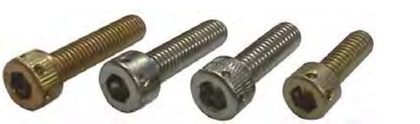
MS24673 screw — cylindrical socket head cap, drilled for safety wire (plain or knurled)
Screw, Cap, Socket Head, Hexagon, Drilled, Corrosion-Resisting Steel, UNF-3A, from MS24673 Rev. D w/ Amendment 1. Every row below is transcribed from the standard and has its own link.
MS24673 at a glance
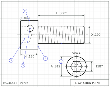
MS24673Engineering drawing · dimensions in inches
Specification
Item
Value
Head
cylindrical socket head cap, drilled for safety wire (plain or knurled)
Drive
hexagon socket
Thread series
fine (UNF-3A)
Material
Austenitic corrosion-resisting steel in accordance with FF-S-86.
Heat treatment
Mechanical properties per FF-S-86 plus the magnetic permeability limit (2.0 max, air = 1.0, H = 200 oersteds, ASTM A 342 indicator). Tensile loads based on 80,000 psi minimum ultimate tensile strength.
Item
Value
Finish
Passivated in accordance with QQ-P-35.
Procurement
FF-S-86
Thread specification
MIL-S-7742
Status
Rev. D (9 Nov 1984) with Amendment 1 (19 Apr 1996). Notice 1 (25 Nov 1998): canceled and superseded by NASM24673; the part numbers are identical (MS24673-1 = NASM24673-1). Earlier revisions marked on the sheet: A (27 Jan 1961), B (7 Jul 1975), C (15 Mar 1976); approved 7 Apr 1960.
Dimensions by size
Dimension, in
.190-32 UNF-3A
.250-28 UNF-3A
.3125-24 UNF-3A
.375-24 UNF-3A
nominal
#10
1/4
5/16
3/8
D body dia
.1840 – .1900
.2435 – .2500
.3053 – .3125
.3678 – .3750
A head dia
.303 – .312
.365 – .375
.457 – .469
.550 – .562
H head height
.185 – .190
.244 – .250
.306 – .312
.368 – .375
S head side height min
.171
.225
.281
.337
J socket across flats
.1562 – .1587
.1875 – .1900
.2500 – .2530
.3125 – .3160
T key engagement min
.090
.120
.151
.182
G wall thickness min
.065
.095
.119
.143
C chamfer or radius max
.005
.008
.008
.008
R fillet extension
.009 – .014
.009 – .014
.012 – .017
.015 – .020
K hole location
.045 – .065
.065 – .085
.084 – .104
.103 – .123
E hole dia
.044 – .050
.044 – .050
.044 – .050
.061 – .067
recommended wire dia
.032 – .040
.032 – .040
.032 – .040
.045 – .057
alignment plug dia
.030
.030
.030
.051
min tensile lbf
1600
2920
4640
7020
holes through head
3
3
3
3
Minimum – maximum as tabulated in MS24673 Rev. D w/ Amendment 1; letters as on the standard's drawing.
Part numbers and lengths
Every part number of MS24673 Rev. D w/ Amendment 1, by thread size, each with its own link.
Dash number from the length table selects thread size and length (1 to 22; -15 is not shown on the sheet)
Notes from the standard
Threads per MIL-S-7742 (as printed); acceptability: complete (full form) threads within two threads of the head, measured with a thread ring gage, on screws above the heavy line in the length table (rows with threaded_to_head = true). Rows below the heavy line carry the maximum grip length LG and minimum body length LB.
Head may or may not be knurled at the manufacturer's option; type of knurling optional. Diameter of a knurled head must not exceed the maximum head diameter.
Drilled hole data: screws #10 (.190) and larger have three (3) holes drilled through the head; the holes lie within the flats of the hexagon socket and shall not break the corners of the socket.
Edges of the holes on the outside of the head are chamfered 45 degrees by 0.010 to 0.020 deep.
Alignment plug (Table I) shall pass completely through the head without deflection.
Tensile strength: loads in pounds based on 80,000 psi minimum ultimate tensile strength, calculated from the stress areas indicated in FED-STD-H28.
Magnetic permeability: 2.0 max (air = 1.0) at a field strength H = 200 oersteds; indicator per ASTM A 342 (Amendment 1, 19 Apr 1996, replaced MIL-I-17214).
Dimensions in inches unless otherwise specified. For design-feature purposes this standard takes precedence over the procurement documents referenced herein.
Scanned sheet: lengths per dash were assigned by row position in the length column (dash numbers print slightly offset from their length rows); grip LG/LB values are read as printed (two decimals).
Dash -15 does not appear on the sheet; the 5/16 column starts at -16 (1.000), and no 5/16 screw shorter than 1.000 is listed.