The Aviation PointTechnical data sheet · theaviationpoint.com/parts/screws/ms16995/
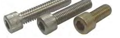
MS16995 screw — cylindrical socket head cap (plain or knurled)
Screw, Cap, Socket Head, Hexagon, Corrosion Resistant Steel, UNC-3A, from MS16995 Rev. H. Every row below is transcribed from the standard and has its own link.
MS16995 at a glance
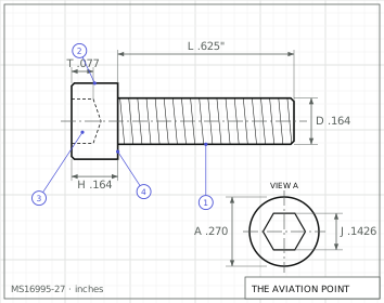
MS16995Engineering drawing · dimensions in inches
Specification
Item
Value
Head
cylindrical socket head cap (plain or knurled)
Drive
hexagon socket
Thread series
coarse (UNC-3A)
Material
Austenitic corrosion resistant steel Type 304 (UNS S30400), 304L (S30403), 305 (S30500), 316 (S31600), 316L (S31603), 384 (S38400) or XM-7 (S30430), chemical composition per ASTM F 593.
Heat treatment
Minimum tensile strength 80,000 psi (load per Table I, from the stress areas of FED-STD-H28/2); yield strength 30,000 psi minimum (0.2 percent offset); minimum hardness HRB 80.
Item
Value
Finish
Passivate per QQ-P-35, or black oxide per MIL-C-13924 Class 4 (not for Type 316 or 316L).
Procurement
FF-S-86
Thread specification
FED-STD-H28/2
Status
Rev. H (25 Apr 1997). Notice 1 (30 Jun 1998): canceled and superseded by NASM16995; the part numbers are identical (MS16995-1 = NASM16995-1). Supersedes MS16995G (27 Jun 1995) and, in part, MS35461.
Dimensions by size
Dimension, in
.0860-56 UNC-3A
.1120-40 UNC-3A
.1380-32 UNC-3A
.1640-32 UNC-3A
.1900-24 UNC-3A
.2500-20 UNC-3A
.3125-18 UNC-3A
.3750-16 UNC-3A
.5000-13 UNC-3A
.6250-11 UNC-3A
nominal
#2
#4
#6
#8
#10
1/4
5/16
3/8
1/2
5/8
D body dia
.0822 – .0860
.1075 – .1120
.1329 – .1380
.1585 – .1640
.1840 – .1900
.2435 – .2500
.3053 – .3125
.3678 – .3750
.4919 – .5000
.6163 – .6250
A head dia
.134 – .140
.176 – .183
.218 – .226
.262 – .270
.303 – .312
.365 – .375
.457 – .469
.550 – .563
.735 – .750
.921 – .936
H head height
.083 – .086
.108 – .112
.134 – .138
.159 – .164
.185 – .190
.244 – .250
.306 – .313
.368 – .375
.492 – .500
.616 – .625
S head side height min
.077
.101
.124
.148
.171
.225
.281
.337
.450
.562
J socket across flats
.0781 – .0791
.0937 – .0952
.1094 – .1111
.1406 – .1426
.1562 – .1587
.1875 – .1900
.2500 – .2530
.3125 – .3160
.3750 – .3790
.5000 – .5050
T key engagement min
.038
.051
.064
.077
.090
.120
.151
.182
.245
.307
G wall thickness min
.029
.038
.047
.056
.065
.095
.119
.143
.190
.238
K chamfer or radius max
.003
.005
.005
.005
.005
.008
.008
.008
.010
.010
F fillet extension
.004 – .008
.005 – .009
.006 – .010
.007 – .012
.009 – .014
.009 – .014
.012 – .017
.015 – .020
.020 – .026
.024 – .032
M basic thread length ref
.625
.7500
.7500
.875
.875
1.000
1.125
1.250
1.500
1.750
min tensile lbf
300
480
730
1120
1400
2540
4190
6200
11300
18100
Minimum – maximum as tabulated in MS16995 Rev. H; letters as on the standard's drawing.
Part numbers and lengths
Every part number of MS16995 Rev. H, by thread size, each with its own link.
.0860-56 UNC-3A4 part numbers · tolerance +.000/-.030
MS16995-1 = .0860-56 UNC-3A, .188 long, passivated; MS16995-1S316 = Type 316/316L, passivated; MS16995-1B = black oxide
Length tolerance, .375 to 1.000
+.000/-.030
Length tolerance, 1.250 to 2.000 (sizes #8, #10, 1/4)
+.000/-.040
Length tolerance, 1.250 to 2.500 (5/16, 3/8)
+.000/-.040
Length tolerance, 2.750 to 3.000 (5/16, 3/8)
+.000/-.060 (no such lengths listed)
Length tolerance, 1.250 to 2.500 (1/2)
+.000/-.060
Length tolerance, 2.750 to 3.000 (1/2)
+.000/-.080
Length tolerance, 1.250 to 2.250 (5/8)
+.000/-.060
Length tolerance, 2.500 to 3.000 (5/8)
+.000/-.080
Dash
Dash number from Table I selects thread size and length (1 to 115, with gaps)
(none)
Material: any 300 series austenitic CRES listed in the material requirement
S316
Material: Type 316 or 316L (marked "316" on the head, sizes #10 and larger)
(none)
Finish: passivated
B
Finish: black oxide coating (not available for Type 316/316L)
Notes from the standard
Thread: Unified external class 3A UNC, FED-STD-H28/2; acceptability per FED-STD-H28/20 System 22. Screws above the dashed lines in Table I (rows with threaded_to_head = true) have complete (full form) threads to within two threads of the head, checked with a thread ring gage.
Rows below the dashed line carry the maximum grip length and minimum body length (rows with grip_max / body_min). The basic thread length M is a reference value controlled by the grip length and L.
Head of screw may be plain or knurled at the manufacturer's option. Hexagon socket; acceptable socket design per Figure 1 (form within 120 degrees minimum included angle at minimum material limit; chamfer or radius K).
Manufacturer's symbol marking on sizes #10 (.1900) and larger, not on bearing surfaces. Type 316/316L sizes #10 and larger are marked "316".
Magnetic permeability when specified: below 2.0 (air = 1.0) at H = 200 oersteds, indicator per ASTM A 342. Cold-worked screws may not meet permeability and strength together.
Dash numbers not listed (for example 5-8, 14-15, 22-24, 31-34, 43-46, 57-60, 73-76, 88-91, 103-106) are not assigned in this sheet.
Table II (interchangeability with MS35461) is transcribed in the interchangeability field.