ASNA0078 at a glance
Where to buy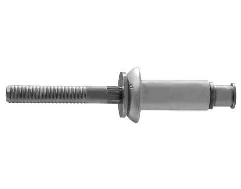
Specification
| Item | Value |
|---|---|
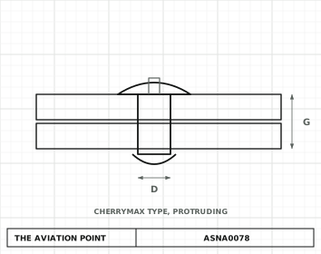
| Type | Blind rivet, bulbed, mechanically locked stem |
| Material | Letter A to F: steel or Monel sleeve, aluminium alloy or Monel (see the cross). Head marks: + = stainless-steel stem with aluminium-alloy sleeve; no mark = steel stem; M = Monel sleeve |
| Locking | Mechanically locked stem with a locking collar |
| Finish | Not stated in the standard data |
| Status | Reference data transcribed from the standard, units marked row by row. Check the issue of the standard in force before design use. |
Dimensions by size
| Dimension, inch first (mm after) | -4 | -5 | -6 |
|---|---|---|---|
| Nominal Ø (code) | 1/8 in (0.1250 in; 3.175 mm) | 5/32 in (0.1562 in; 3.969 mm) | 3/16 in (0.1875 in; 4.762 mm) |
| Printed name | 3.2 mm (printed in the tooling block) | 4 mm (printed in the tooling block) | 4.8 mm (printed in the tooling block) |
| Hole † | 0.1291–0.1319 in (3.28–3.35 mm†) | 0.1602–0.1642 in (4.07–4.17 mm†) | 0.1921–0.1961 in (4.88–4.98 mm†) |
| Drill (chart) | #30 (0.1285 in; 3.26 mm), just under the minimum: gauge the hole | #20 (0.1610 in; 4.09 mm) | #10 (0.1935 in; 4.91 mm) |
Units: no mark = printed in mm and stated by the standard. † = printed with no unit; the inch value is our conversion, reading the figure as mm. Nominal Ø is our reading of the inch code (1/32 in for diameters, 1/16 in for grips). Drill: from the site drill chart, inside the hole range except code 4, where the chart's #30 (0.1285 in) is just under the printed minimum (a drill cuts slightly oversize): gauge the finished hole.
Part numbers
Part numbers by diameter code and grip, letter A shown; swap the letter and add X as the code table says.
-4 · 1/8 in nominal14 part numbers
| Part no. | Grip, in (mm printed) |
|---|---|
| ASNA0078A401 | to 0.062 (to 1.57) |
| ASNA0078A402 | 0.063–0.125 (1.60–3.18) |
| ASNA0078A403 | 0.126–0.187 (3.20–4.75) |
| ASNA0078A404 | 0.188–0.250 (4.78–6.35) |
| ASNA0078A405 | 0.251–0.312 (6.37–7.92) |
| ASNA0078A406 | 0.313–0.375 (7.95–9.52) |
| ASNA0078A407 | 0.376–0.437 (9.55–11.10) |
| ASNA0078A408 | 0.438–0.500 (11.13–12.70) |
| ASNA0078A409 | 0.501–0.562 (12.73–14.27) |
| ASNA0078A410 | 0.563–0.625 (14.30–15.88) |
| ASNA0078A411 | 0.626–0.687 (15.90–17.45) |
| ASNA0078A412 | 0.688–0.750 (17.48–19.05) |
| ASNA0078A413 | 0.751–0.812 (19.07–20.62) |
| ASNA0078A414 | 0.813–0.875 (20.65–22.22) |
-5 · 5/32 in nominal14 part numbers
| Part no. | Grip, in (mm printed) |
|---|---|
| ASNA0078A501 | to 0.062 (to 1.57) |
| ASNA0078A502 | 0.063–0.125 (1.60–3.18) |
| ASNA0078A503 | 0.126–0.187 (3.20–4.75) |
| ASNA0078A504 | 0.188–0.250 (4.78–6.35) |
| ASNA0078A505 | 0.251–0.312 (6.37–7.92) |
| ASNA0078A506 | 0.313–0.375 (7.95–9.52) |
| ASNA0078A507 | 0.376–0.437 (9.55–11.10) |
| ASNA0078A508 | 0.438–0.500 (11.13–12.70) |
| ASNA0078A509 | 0.501–0.562 (12.73–14.27) |
| ASNA0078A510 | 0.563–0.625 (14.30–15.88) |
| ASNA0078A511 | 0.626–0.687 (15.90–17.45) |
| ASNA0078A512 | 0.688–0.750 (17.48–19.05) |
| ASNA0078A513 | 0.751–0.812 (19.07–20.62) |
| ASNA0078A514 | 0.813–0.875 (20.65–22.22) |
-6 · 3/16 in nominal14 part numbers
| Part no. | Grip, in (mm printed) |
|---|---|
| ASNA0078A601 | to 0.062 (to 1.57) |
| ASNA0078A602 | 0.063–0.125 (1.60–3.18) |
| ASNA0078A603 | 0.126–0.187 (3.20–4.75) |
| ASNA0078A604 | 0.188–0.250 (4.78–6.35) |
| ASNA0078A605 | 0.251–0.312 (6.37–7.92) |
| ASNA0078A606 | 0.313–0.375 (7.95–9.52) |
| ASNA0078A607 | 0.376–0.437 (9.55–11.10) |
| ASNA0078A608 | 0.438–0.500 (11.13–12.70) |
| ASNA0078A609 | 0.501–0.562 (12.73–14.27) |
| ASNA0078A610 | 0.563–0.625 (14.30–15.88) |
| ASNA0078A611 | 0.626–0.687 (15.90–17.45) |
| ASNA0078A612 | 0.688–0.750 (17.48–19.05) |
| ASNA0078A613 | 0.751–0.812 (19.07–20.62) |
| ASNA0078A614 | 0.813–0.875 (20.65–22.22) |
Part number

How to read it
| Segment | Reads as ASNA0078A403X |
|---|---|
| ASNA0078 Standard | Bulbed blind rivet, mechanically locked stem with locking collar (CherryMAX type). Head: protruding, flattened round.Unit of the code: None: the number of the standardFrom: The standard |
| A Material | Material letter A (CR3212 / CR3213, NAS9302B / NAS9301B). Letters B to F map to the other CherryMAX and Monel families (public decoder table)Unit of the code: Letter, no unitFrom: Letter list; the meanings marked as a reading come from the partner standards |
| 4 Diameter | 1/8 in nominal: 4 × 1/32 in (0.125 in · 3.175 mm, our conversion); hole 0.129–0.132 in · 3.28–3.35 mm (mm by context).Unit of the code: 1/32 in, by the inch dash logic (the standard only prints rounded mm); inch and mm values are our conversionFrom: Diameter and hole table (Dimensions by size, above) |
| 03 Grip | Max grip 3/16 in; stack 0.126–0.187 in · 3.20–4.75 mm.Unit of the code: 1/16 in steps, maximum grip (inch dash logic); the range is printed in mmFrom: Grip table (Part numbers, above) |
| X Oversize | Oversize, +1/64 in on the diameter (public decoder source); the head carries an inverted TUnit of the code: Letter, no unitFrom: Oversize letter (the head carries an inverted T) |
Worked example. ASNA0078A403X reads: ASNA0078 CherryMAX-type blind rivet, protruding · A CherryMAX series CR3213 · 4 1/8 in, hole 3.28–3.35 mm, drill #30 · 03 max 3/16 in, stack 3.20–4.75 mm · X +1/64 in shank.
From a measured hole or stack to the code
- Hole to diameter code. Measure the hole and take the code whose hole range holds it, never the nominal: 4 → 3.28–3.35 · 5 → 4.07–4.17 · 6 → 4.88–4.98 mm.
- Stack to grip code. Measure the total thickness to be joined with a grip gauge and take the code whose range holds it, for that diameter: a 4.00 mm stack with diameter 4 → grip 03 (3.20–4.75 mm).
If a segment is missing
- Without the standard number the codes cannot be read: grip code 04 is 4.78–6.35 mm on ASNA0077/0078, 5.56–7.16 mm on ASNA0026/0027, 5.59–7.14 mm on ASNA0081/0082.
- No material letter: the number is incomplete; letters A to F name different CherryMAX-type families.
- No diameter or grip code: the number names the family only, not a part; a default size is not given by the standard.
- No grip code: the number is incomplete; a default grip is not given by the standard.
- No X: standard size. X = oversize, +1/64 in: no hole size is printed for the oversize, so it is never drilled to the standard hole.
What each code means
| Part | Meaning |
|---|---|
| Format | ASNA0078<material><dash><os> |
| A | Material: Material letter A (CR3212 / CR3213, NAS9302B / NAS9301B). Letters B to F map to the other CherryMAX and Monel families (public decoder table) |
| (none) | Os: Standard size |
| X | Os: Oversize, +1/64 in on the diameter (public decoder source); the head carries an inverted T |
| Example | ASNA0078A403X — Material A, diameter code 4 (1/8 in nominal), grip code 03 (0.126–0.187 in; 3.20–4.75 mm printed), oversize X |
Tools
| Tool or head | Type | Codes |
|---|---|---|
| G747 (stroke 0.437 in; 11.1 mm printed) | pneumatic | 4, 5, 6 |
| G27 | hand tool | 4 only |
| H701B-456 | straight head | 4, 5, 6 |
| H747-456 + insert 782-456 | straight head | 4, 5, 6 |
| H753A-456 | right-angle (90°) head | 4, 5, 6 |
| H782 + insert 782-456 | offset head | 4, 5, 6 |
| H781-456 | offset head, restricted use | 4, 5, 6 (nose setback L = rivet diameter, mandatory for code 4) |
Use H781-456 only where access forces it.
Inspection limits
| Check | Limit, inch first |
|---|---|
| Gap under a protruding head | Not more than 0.004 in (0.10 mm, printed in mm) on no more than 10 % of the row and never on 2 consecutive rivets |
| Stem and collar against the head top | Protrusion 0.25 maximum, recess 0.50 maximum (0.38 for code 4). Unit not stated (mm by context): not converted |
| Convex surfaces | Measure the head gap along the straight generatrices |
| Stem shaving | Only exceptionally and only if the drawing calls for it |
| Locking collar | Check that it is present |
Limits as the standard gives them; the aircraft's SRM governs.
Notes from the standard
- Part number: ASNA0078 + material letter (A to F) + diameter code (4, 5 or 6) + grip code (01 and up) + optional X for oversize. The rows show letter A.
- Grips start at 01 (ASNA0077 starts at 02). Grip 01 has no minimum and tops out at 0.062 in (1.57 mm printed); each code n above it tops out at n/16 in: code 4 is 0.188–0.250 in (4.78–6.35 mm printed).
- Protruding head: no countersink; deburr the hole edge.
- The printed names 3,2 · 4 · 4,8 are mm (stated in the tooling block): 3,2 mm is 1/8 in rounded. No oversize hole size is printed.
- Units: no mark = printed in mm and stated by the standard. † = printed with no unit; the inch value is our conversion, reading the figure as mm. Nominal Ø is our reading of the inch code (1/32 in for diameters, 1/16 in for grips). Drill: from the site drill chart, inside the hole range except code 4, where the chart's #30 (0.1285 in) is just under the printed minimum (a drill cuts slightly oversize): gauge the finished hole.
Where to buy
Distributors coming soon.
Keep going
Calculators
Guides
How to do it
Tools
Data sheets
Books
Buy
Distributors coming soon.
Sources
- ASNA0078 standard (ASNA series) — Codes, tables, tooling and inspection limits transcribed into the reference data of The Aviation Point. The text of the standard is not reproduced. Check the issue in force before design use.
- Cherry Aerospace pulling-head sheets — -MBU heads for the U type and the titanium -8 offset head; the same data feeds the Cherry pulling head selector.
- US federal item records (NSN) and distributor listings — Partner numbers. The evidence is named on each cross line: federal NSN record, manufacturer catalogue, or distributor listing (alternate, not identical).