MS3102 at a glance
Where to buy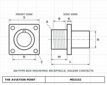
Specification
| Item | Value |
|---|---|
| Type | Circular connector receptacle, box mounting, solder contacts |
| Status | Cancelled by Notice 3 (December 2009) and replaced by SAE-AS31021; inactive for new design since Notice 1 (19 June 1999). Check the current issue before design use. |
Dimensions by size
| Dimension, in | 8S | 10S | 10SL | 12S | 12 | 14S | 14 | 16S | 16 | 18 | 20 | 22 | 24 | 28 | 32 | 36 | 40 | 44 | 48 |
|---|---|---|---|---|---|---|---|---|---|---|---|---|---|---|---|---|---|---|---|
| A — A coupling thread | 1/2-28 | 5/8-24 | 5/8-24 | 3/4-20 | 3/4-20 | 7/8-20 | 7/8-20 | 1-20 | 1-20 | 1-1/8-18 | 1-1/4-18 | 1-3/8-18 | 1-1/2-18 | 1-3/4-18 | 2-18 | 2-1/4-16 | 2-1/2-16 | 2-3/4-16 | 3-16 |
| B — B usable thread, min | .375 | .375 | .375 | .375 | .625 | .375 | .625 | .375 | .625 | .625 | .625 | .625 | .625 | .625 | .625 | .625 | .625 | .625 | .625 |
| D — D dia inside, +.015 −.000 | .370 | .448 | .448 | .557 | .557 | .682 | .682 | .807 | .807 | .932 | 1.058 | 1.182 | 1.307 | 1.526 | 1.776 | 1.995 | 2.245 | 2.495 | 2.745 |
| I — I dia insert, max | .250 | .320 | .448 | .448 | .448 | .525 | .525 | .650 | .650 | .770 | .925 | 1.020 | 1.145 | 1.365 | 1.615 | 1.830 | 2.045 | 2.300 | 2.550 |
| JJ — JJ insert location, +.031 −.000 | .562 | .562 | .562 | .562 | .750 | .562 | .750 | .562 | .750 | .750 | .750 | .750 | .750 | .750 | .750 | .750 | .750 | .750 | .750 |
| K max — K mounting flange thickness, max | .156 | .156 | .156 | .156 | .156 | .156 | .156 | .156 | .156 | .203 | .203 | .203 | .203 | .203 | .359 | .359 | .359 | .359 | .359 |
| K min — K mounting flange thickness, min | .062 | .062 | .062 | .062 | .062 | .062 | .062 | .062 | .062 | .094 | .094 | .094 | .094 | .094 | .125 | .125 | .125 | .125 | .125 |
| L — L overall length, max | 1.191 | 1.191 | 1.191 | 1.191 | 1.713 | 1.191 | 1.713 | 1.191 | 1.750 | 1.938 | 1.938 | 1.938 | 1.938 | 1.938 | 1.938 | 1.938 | 1.938 | 2.188 | 2.188 |
| M — M mounting flange location, +.031 −.000 | .562 | .562 | .562 | .562 | .750 | .562 | .750 | .562 | .750 | .750 | .750 | .750 | .812 | .812 | .875 | .875 | .875 | .875 | .875 |
| N — N dia outside, +.000 −.188 | .532 | .656 | .782 | .782 | .782 | .906 | .906 | 1.032 | 1.032 | 1.156 | 1.282 | 1.406 | 1.532 | 1.782 | 2.032 | 2.282 | 2.532 | 2.782 | 3.032 |
| O — O dia mounting hole (ref.) | .562 | .688 | .812 | .812 | .812 | .938 | .938 | 1.062 | 1.062 | 1.188 | 1.312 | 1.438 | 1.562 | 1.812 | 2.062 | 2.312 | 2.562 | 2.812 | 3.062 |
| P — P key height, +.015 −.000 | .130 | .165 | .165 | .224 | .224 | .263 | .263 | .325 | .325 | .385 | .463 | .510 | .573 | .683 | .808 | .915 | 1.023 | 1.150 | 1.275 |
| R — R mounting holes, center to center, ±.005 | .594 | .719 | .719 | .812 | .812 | .906 | .906 | .969 | .969 | 1.062 | 1.156 | 1.250 | 1.375 | 1.562 | 1.750 | 1.938 | 2.188 | 2.375 | 2.625 |
| S — S flange side length, ±.031 | .875 | 1.000 | 1.000 | 1.094 | 1.094 | 1.188 | 1.188 | 1.281 | 1.281 | 1.375 | 1.500 | 1.625 | 1.750 | 2.000 | 2.250 | 2.500 | 2.750 | 3.000 | 3.250 |
| T — T dia mounting bolt hole, +.010 −.005 | .120 | .120 | .120 | .120 | .120 | .120 | .120 | .120 | .120 | .120 | .120 | .120 | .147 | .147 | .173 | .173 | .173 | .173 | .173 |
Classes A and C, dimensions in inches; letters as on the standard's drawing. Classes K, E and R follow below.
Part numbers
Basic part number by class and shell size. The complete number adds a dash, the insert arrangement number, the style P or S and, for an alternate insert position, W, X, Y or Z. The standard governs.
8S5 part numbers
| Part no. | Class | Coupling thread |
|---|---|---|
| MS3102A8S | A | 1/2-28 |
| MS3102C8S | C | 1/2-28 |
| MS3102K8S | K | 1/2-28 |
| MS3102E8S | E | 1/2-28 |
| MS3102R8S | R | 1/2-28 |
10S5 part numbers
| Part no. | Class | Coupling thread |
|---|---|---|
| MS3102A10S | A | 5/8-24 |
| MS3102C10S | C | 5/8-24 |
| MS3102K10S | K | 5/8-24 |
| MS3102E10S | E | 5/8-24 |
| MS3102R10S | R | 5/8-24 |
10SL5 part numbers
| Part no. | Class | Coupling thread |
|---|---|---|
| MS3102A10SL | A | 5/8-24 |
| MS3102C10SL | C | 5/8-24 |
| MS3102K10SL | K | 5/8-24 |
| MS3102E10SL | E | 5/8-24 |
| MS3102R10SL | R | 5/8-24 |
12S5 part numbers
| Part no. | Class | Coupling thread |
|---|---|---|
| MS3102A12S | A | 3/4-20 |
| MS3102C12S | C | 3/4-20 |
| MS3102K12S | K | 3/4-20 |
| MS3102E12S | E | 3/4-20 |
| MS3102R12S | R | 3/4-20 |
125 part numbers
| Part no. | Class | Coupling thread |
|---|---|---|
| MS3102A12 | A | 3/4-20 |
| MS3102C12 | C | 3/4-20 |
| MS3102K12 | K | 3/4-20 |
| MS3102E12 | E | 3/4-20 |
| MS3102R12 | R | 3/4-20 |
14S5 part numbers
| Part no. | Class | Coupling thread |
|---|---|---|
| MS3102A14S | A | 7/8-20 |
| MS3102C14S | C | 7/8-20 |
| MS3102K14S | K | 7/8-20 |
| MS3102E14S | E | 7/8-20 |
| MS3102R14S | R | 7/8-20 |
145 part numbers
| Part no. | Class | Coupling thread |
|---|---|---|
| MS3102A14 | A | 7/8-20 |
| MS3102C14 | C | 7/8-20 |
| MS3102K14 | K | 7/8-20 |
| MS3102E14 | E | 7/8-20 |
| MS3102R14 | R | 7/8-20 |
16S5 part numbers
| Part no. | Class | Coupling thread |
|---|---|---|
| MS3102A16S | A | 1-20 |
| MS3102C16S | C | 1-20 |
| MS3102K16S | K | 1-20 |
| MS3102E16S | E | 1-20 |
| MS3102R16S | R | 1-20 |
165 part numbers
| Part no. | Class | Coupling thread |
|---|---|---|
| MS3102A16 | A | 1-20 |
| MS3102C16 | C | 1-20 |
| MS3102K16 | K | 1-20 |
| MS3102E16 | E | 1-20 |
| MS3102R16 | R | 1-20 |
185 part numbers
| Part no. | Class | Coupling thread |
|---|---|---|
| MS3102A18 | A | 1-1/8-18 |
| MS3102C18 | C | 1-1/8-18 |
| MS3102K18 | K | 1-1/8-18 |
| MS3102E18 | E | 1-1/8-18 |
| MS3102R18 | R | 1-1/8-18 |
205 part numbers
| Part no. | Class | Coupling thread |
|---|---|---|
| MS3102A20 | A | 1-1/4-18 |
| MS3102C20 | C | 1-1/4-18 |
| MS3102K20 | K | 1-1/4-18 |
| MS3102E20 | E | 1-1/4-18 |
| MS3102R20 | R | 1-1/4-18 |
225 part numbers
| Part no. | Class | Coupling thread |
|---|---|---|
| MS3102A22 | A | 1-3/8-18 |
| MS3102C22 | C | 1-3/8-18 |
| MS3102K22 | K | 1-3/8-18 |
| MS3102E22 | E | 1-3/8-18 |
| MS3102R22 | R | 1-3/8-18 |
245 part numbers
| Part no. | Class | Coupling thread |
|---|---|---|
| MS3102A24 | A | 1-1/2-18 |
| MS3102C24 | C | 1-1/2-18 |
| MS3102K24 | K | 1-1/2-18 |
| MS3102E24 | E | 1-1/2-18 |
| MS3102R24 | R | 1-1/2-18 |
285 part numbers
| Part no. | Class | Coupling thread |
|---|---|---|
| MS3102A28 | A | 1-3/4-18 |
| MS3102C28 | C | 1-3/4-18 |
| MS3102K28 | K | 1-3/4-18 |
| MS3102E28 | E | 1-3/4-18 |
| MS3102R28 | R | 1-3/4-18 |
325 part numbers
| Part no. | Class | Coupling thread |
|---|---|---|
| MS3102A32 | A | 2-18 |
| MS3102C32 | C | 2-18 |
| MS3102K32 | K | 2-18 |
| MS3102E32 | E | 2-18 |
| MS3102R32 | R | 2-18 |
365 part numbers
| Part no. | Class | Coupling thread |
|---|---|---|
| MS3102A36 | A | 2-1/4-16 |
| MS3102C36 | C | 2-1/4-16 |
| MS3102K36 | K | 2-1/4-16 |
| MS3102E36 | E | 2-1/4-16 |
| MS3102R36 | R | 2-1/4-16 |
Part number
What each code means
| Part | Meaning |
|---|---|
| Format | MS3102<cls><dash>-(insert)<style><pos> |
| A | Cls: Solid shell |
| C | Cls: Pressurized |
| K | Cls: Firewall |
| E | Cls: Environment resistant |
| R | Cls: Environment resistant (replaces class E) |
| P | Style: Pin insert |
| S | Style: Socket insert |
| Pos: Normal insert position | |
| W | Pos: Alternate insert position W |
| X | Pos: Alternate insert position X |
| Y | Pos: Alternate insert position Y |
| Z | Pos: Alternate insert position Z |
| Example | MS3102R18-5SY — Class R (environment resistant) receptacle, shell size 18, insert arrangement 18-5 (MIL-STD-1651), socket insert, alternate insert position Y |
Class K, firewall: dimensions
| Shell size | A coupling thread | B usable thread, min | D dia inside +.015 −.000 | I dia insert, max | JJ insert location +.031 −.000 | K flange thickness, min | L overall length, max | M flange location +.031 −.000 | N dia outside +.000 −.188 | O dia mounting hole (ref.) | P key height +.015 −.000 | R hole centers ±.005 | S side length ±.031 | T dia bolt hole +.010 −.005 |
|---|---|---|---|---|---|---|---|---|---|---|---|---|---|---|
| 8S | 1/2-28 | .375 | .370 | .250 | .562 | .062 | 1.375 | .562 | .532 | .562 | .130 | .594 | .875 | .150 |
| 10S | 5/8-24 | .375 | .448 | .320 | .562 | .062 | 1.438 | .562 | .656 | .688 | .165 | .719 | 1.000 | .150 |
| 10SL | 5/8-24 | .375 | .448 | .448 | .562 | .062 | 1.438 | .562 | .782 | .812 | .165 | .719 | 1.000 | .150 |
| 12S | 3/4-20 | .375 | .557 | .448 | .562 | .062 | 1.438 | .562 | .782 | .812 | .224 | .812 | 1.094 | .150 |
| 12 | 3/4-20 | .625 | .557 | .448 | .750 | .062 | 1.812 | .750 | .782 | .812 | .224 | .812 | 1.094 | .150 |
| 14S | 7/8-20 | .375 | .682 | .525 | .562 | .062 | 1.438 | .562 | .906 | .938 | .263 | .906 | 1.188 | .150 |
| 14 | 7/8-20 | .625 | .682 | .525 | .750 | .062 | None | .750 | .906 | .938 | .263 | .906 | 1.188 | .150 |
| 16S | 1-20 | .375 | .807 | .650 | .562 | .062 | 1.438 | .562 | 1.032 | 1.062 | .325 | .969 | 1.281 | .150 |
| 16 | 1-20 | .625 | .807 | .650 | .750 | .062 | 2.062 | .750 | 1.032 | 1.062 | .325 | .969 | 1.281 | .150 |
| 18 | 1-1/8-18 | .625 | .932 | .770 | .750 | .062 | 2.062 | .750 | 1.156 | 1.188 | .385 | 1.062 | 1.375 | .177 |
| 20 | 1-1/4-18 | .625 | 1.058 | .925 | .750 | .078 | 2.250 | .750 | 1.282 | 1.312 | .463 | 1.156 | 1.500 | .177 |
| 22 | 1-3/8-18 | .625 | 1.182 | 1.020 | .750 | .078 | 2.250 | .750 | 1.406 | 1.438 | .510 | 1.250 | 1.625 | .177 |
| 24 | 1-1/2-18 | .625 | 1.307 | 1.145 | .750 | .078 | 2.250 | .812 | 1.532 | 1.562 | .573 | 1.375 | 1.750 | .177 |
| 28 | 1-3/4-18 | .625 | 1.526 | 1.365 | .750 | .078 | 2.250 | .812 | 1.782 | 1.812 | .683 | 1.562 | 2.000 | .177 |
| 32 | 2-18 | .625 | 1.776 | 1.615 | .750 | .078 | 2.250 | .875 | 2.032 | 2.062 | .808 | 1.750 | 2.250 | .209 |
| 36 | 2-1/4-16 | .625 | 1.995 | 1.830 | .750 | .125 | 2.250 | .875 | 2.282 | 2.312 | .915 | 1.938 | 2.500 | .209 |
| 40 | 2-1/2-16 | .625 | 2.245 | 2.045 | .750 | .125 | 2.250 | .875 | 2.532 | 2.562 | 1.023 | 2.188 | 2.750 | .209 |
Class E, environment resistant: dimensions
| Shell size | A coupling thread | B usable thread, min | D dia inside +.015 −.000 | I dia insert, max | J internal shell shoulder +.031 −.000 | JJ insert location ±.031 | K flange thickness, max | K flange thickness, min | L overall length, max | M flange location +.031 −.000 | N dia outside +.000 −.188 | O dia mounting hole (ref.) | P key height +.015 −.000 | R hole centers ±.005 | S side length ±.031 | T dia bolt hole +.010 −.005 |
|---|---|---|---|---|---|---|---|---|---|---|---|---|---|---|---|---|
| 8S | 1/2-28 | .375 | .370 | .250 | .562 | .484 | .156 | .078 | 1.188 | .562 | .532 | .562 | .130 | .594 | .875 | .120 |
| 10S | 5/8-24 | .375 | .448 | .320 | .562 | .484 | .156 | .078 | 1.188 | .562 | .656 | .688 | .165 | .719 | 1.000 | .120 |
| 10SL | 5/8-24 | .375 | .448 | .448 | .562 | .484 | .156 | .078 | 1.188 | .562 | .782 | .812 | .165 | .719 | 1.000 | .120 |
| 12S | 3/4-20 | .375 | .557 | .448 | .562 | .484 | .156 | .078 | 1.188 | .562 | .782 | .812 | .224 | .812 | 1.094 | .120 |
| 12 | 3/4-20 | .625 | .557 | .448 | .750 | .672 | .156 | .078 | 1.625 | .750 | .782 | .812 | .224 | .812 | 1.094 | .120 |
| 14S | 7/8-20 | .375 | .682 | .525 | .562 | .484 | .156 | .078 | 1.188 | .562 | .906 | .938 | .263 | .906 | 1.188 | .120 |
| 14 | 7/8-20 | .625 | .682 | .525 | .750 | .672 | .156 | .078 | 1.625 | .750 | .906 | .938 | .263 | .906 | 1.188 | .120 |
| 16S | 1-20 | .375 | .807 | .650 | .562 | .484 | .156 | .078 | 1.188 | .562 | 1.032 | 1.062 | .325 | .969 | 1.281 | .120 |
| 16 | 1-20 | .625 | .807 | .650 | .750 | .672 | .156 | .078 | 1.625 | .750 | 1.032 | 1.062 | .325 | .969 | 1.281 | .120 |
| 18 | 1-1/8-18 | .625 | .932 | .770 | .750 | .672 | .203 | .094 | 1.938 | .750 | 1.156 | 1.188 | .385 | 1.062 | 1.375 | .120 |
| 20 | 1-1/4-18 | .625 | 1.058 | .925 | .750 | .672 | .203 | .094 | 1.938 | .750 | 1.282 | 1.312 | .463 | 1.156 | 1.500 | .120 |
| 22 | 1-3/8-18 | .625 | 1.182 | 1.020 | .750 | .672 | .203 | .094 | 1.938 | .750 | 1.406 | 1.438 | .510 | 1.250 | 1.625 | .120 |
| 24 | 1-1/2-18 | .625 | 1.307 | 1.145 | .750 | .672 | .203 | .094 | 1.938 | .812 | 1.532 | 1.562 | .573 | 1.375 | 1.750 | .147 |
| 28 | 1-3/4-18 | .625 | 1.526 | 1.365 | .750 | .672 | .203 | .094 | 1.938 | .812 | 1.782 | 1.812 | .683 | 1.562 | 2.000 | .147 |
| 32 | 2-18 | .625 | 1.776 | 1.615 | .750 | .672 | .359 | .125 | 1.938 | .875 | 2.032 | 2.062 | .808 | 1.750 | 2.250 | .173 |
| 36 | 2-1/4-16 | .625 | 1.995 | 1.830 | .750 | .672 | .359 | .125 | 1.938 | .875 | 2.282 | 2.312 | .915 | 1.938 | 2.500 | .173 |
| 40 | 2-1/2-16 | .625 | 2.245 | 2.047 | .750 | .672 | .359 | .125 | 1.938 | .875 | 2.532 | 2.562 | 1.023 | 2.188 | 2.750 | .173 |
N: shell sizes 36 and 40, +.000 −.250.
Class R, environment resistant: dimensions
| Shell size | A coupling thread | B usable thread, min | D dia inside +.015 −.000 | I dia insert, max | J internal shell shoulder +.031 −.000 | JJ insert location ±.031 | K flange thickness, max | K flange thickness, min | L overall length, max | M flange location +.031 −.000 | N dia outside +.000 −.188 | O dia mounting hole (ref.) | P key height +.015 −.000 | R hole centers ±.005 | S side length ±.031 | T dia bolt hole +.010 −.005 |
|---|---|---|---|---|---|---|---|---|---|---|---|---|---|---|---|---|
| 8S | 1/2-28 | .375 | None | .250 | .562 | .484 | .156 | .078 | 1.219 | .562 | .532 | .562 | .130 | .594 | .875 | .120 |
| 10S | 5/8-24 | .375 | .448 | .320 | .562 | .484 | .156 | .078 | 1.219 | .562 | .656 | None | .165 | .719 | 1.000 | .120 |
| 10SL | 5/8-24 | .375 | .448 | .448 | .562 | .484 | .156 | .078 | 1.219 | .562 | .782 | .812 | .165 | .719 | 1.000 | .120 |
| 12S | 3/4-20 | .375 | .557 | .448 | .562 | .484 | .156 | .078 | 1.219 | .562 | .782 | .812 | .224 | .812 | 1.094 | .120 |
| 12 | 3/4-20 | .625 | .557 | .448 | .750 | .672 | .156 | .078 | 1.625 | .750 | .782 | .812 | .224 | .812 | 1.094 | .120 |
| 14S | 7/8-20 | .375 | None | .525 | .562 | .484 | .156 | .078 | 1.219 | .562 | .906 | .938 | .263 | .906 | 1.188 | .120 |
| 14 | 7/8-20 | .625 | None | .525 | .750 | .672 | .156 | .078 | 1.625 | .750 | .906 | .938 | .263 | .906 | 1.188 | .120 |
| 16S | 1-20 | .375 | .807 | .650 | .562 | .484 | .156 | .078 | 1.219 | .562 | 1.032 | 1.062 | .325 | .969 | 1.281 | .120 |
| 16 | 1-20 | .625 | .807 | .650 | .750 | .672 | .156 | .078 | 1.625 | .750 | 1.032 | 1.062 | .325 | .969 | 1.281 | .120 |
| 18 | 1-1/8-18 | .625 | .932 | .770 | .750 | .672 | .203 | .094 | 1.938 | .750 | 1.156 | 1.188 | .385 | 1.062 | 1.375 | .120 |
| 20 | 1-1/4-18 | .625 | 1.058 | .925 | .750 | .672 | .203 | .094 | 1.938 | .750 | 1.282 | 1.312 | .463 | 1.156 | 1.500 | .120 |
| 22 | 1-3/8-18 | .625 | None | 1.020 | .750 | .672 | .203 | .094 | 1.938 | .750 | 1.406 | 1.438 | .510 | 1.250 | 1.625 | .120 |
| 24 | 1-1/2-18 | .625 | 1.307 | 1.145 | .750 | .672 | .203 | .094 | 1.938 | .812 | 1.532 | 1.562 | .573 | 1.375 | 1.750 | .147 |
| 28 | 1-3/4-18 | .625 | 1.526 | 1.365 | .750 | .672 | .203 | .094 | 1.938 | .812 | 1.782 | 1.812 | .683 | 1.562 | 2.000 | .147 |
| 32 | 2-18 | .625 | 1.776 | 1.615 | .750 | .672 | .359 | .125 | 1.938 | .875 | 2.032 | 2.062 | .808 | 1.750 | 2.250 | .173 |
| 36 | 2-1/4-16 | .625 | 1.995 | 1.830 | .750 | .672 | .359 | .125 | 1.938 | .875 | 2.282 | 2.312 | .915 | 1.938 | 2.500 | .173 |
| 40 | 2-1/2-16 | .625 | 2.245 | 2.047 | .750 | .672 | .359 | .125 | 1.938 | .875 | 2.532 | 2.562 | 1.023 | 2.188 | 2.750 | .173 |
N: shell sizes 36 and 40, +.000 −.250.
Notes from the standard
- Dimensions in inches. Unless otherwise specified, tolerances: decimals ±.016.
- Insert arrangements per MIL-STD-1651. Style P is a pin insert, S a socket insert; W, X, Y or Z marks an alternate insert position (no letter for the normal position).
- Classes A and C: a socket insert of hard material is .016 maximum beyond or .032 maximum below the shell face; a socket insert of resilient material extends .047 +.000 −.047 beyond the shell. Where resilient inserts are used, JJ may be .109 less than shown.
- Classes A, C, E and R: N tolerance for shell sizes 36 and 40 is +.000 −.250.
- Classes A and C in sizes 8S to 40 and class E were cancelled after 1 Jan 1991; replacement: MS3102R (supply allowed until 1 Jan 1992 or until inventories were exhausted, whichever came first). Classes A and C in sizes 44 and 48 are inactive for new design; classes K and R are inactive for new design after 1 Jan 1991. For new design: MS3452W (classes A, C, E and R) or MS3452K (class K); for shipboard jacketed cable: MS3402.
- MS3102A (or C) replaces and is interchangeable with AN3102A (or C); MS3102K with AN3102K; MS3102E with AN3102E; MS3102R with MS3102E and AN3102E.
- Approved data governs. Use the part the drawing, SRM or IPC calls for.
Where to buy
AmericaDistributor coming soonOur partner for this region is on its way
EuropeDistributor coming soonOur partner for this region is on its way
OceaniaDistributor coming soonOur partner for this region is on its way
Distributors coming soon.
Sources
- MS3102 Rev. E, 20 Aug 1992 — Connector, Receptacle, Electric, Box Mounting, Solder Contacts, AN Type — dimensions, part numbers and notes. Public domain, distribution unlimited.
Educational reference only. not approved data. Always consult the applicable SRM, AMM, or AC 43.13-1B and your certifying authority.