The Aviation PointTechnical data sheet · theaviationpoint.com/parts/electrical/ms3057/
MS3057 — connector cable clamps, types A to D
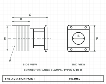
MS3057: cable clamps for AN-type circular connectors: type A strain relief, type B grounding cable seal, type C strain-relief cable seal and type D heavy-duty high-shock clamp, with dimensions by dash number.
Type A: aluminum alloy, QQ-A-591 alloy no. 13. Types B and C: body aluminum alloy (QQ-A-225/5 temper T4, QQ-A-601 or QQ-A-591, alloy no. 13, 218, 380 or SC114A), sleeve aluminum (AMS4025 or QQ-A-225), gland rubber AMS3209 (durometer A 70 ±5), retaining ring brass SAE 70, hard temper; type C clamping bars aluminum QQ-A-250/8 temper H32. Type D: body and saddle aluminum alloy QQ-A-591 (comp. 13, 380 or A380), clamp screws AISI 300 series stainless steel.
Finish
Type A per MIL-C-5015. Types B and C: body, screws and washers cadmium plate QQ-P-416 type II class 3, dull olive drab, electrically conductive; sleeve per MIL-C-5541. Type D by finish code.
Status
Inactive for design after 1 July 1982; the standard directs MIL-C-85049/1, /2, /41 and /42 and states its cancellation after 1 July 1984. Check the current issue before design use.
Dimensions by size
Dimension, in
-3A
-4A
-6A
-8A
-10A
-12A
-16A
-20A
-24A
-28A
-32A
-40A
A — A thread
.500-28 UNEF-2B
.625-24 UNEF-2B
.750-20 UNEF-2B
.875-20 UNEF-2B
1.000-20 UNEF-2B
1.188-18 UNEF-2B
1.438-18 UNEF-2B
1.750-18 UNS-2B
2.000-18 UNS-2B
2.250-16 UN-2B
2.500-16 UN-2B
3.000-16 UN-2B
B — B, max
.250
.312
.438
.562
.625
.750
.938
1.250
1.375
1.625
1.875
2.375
C — C
.047
.062
.078
.109
.125
.156
.188
.250
.297
.328
.375
.453
D — D
.406
.406
.406
.406
.406
.406
.406
.469
.531
.531
.594
.656
E — E dia, ±.031
.688
.812
.969
1.094
1.188
1.375
1.656
2.031
2.219
2.500
2.781
3.281
F — F, ±.031
.812
.875
1.062
1.156
1.250
1.469
1.688
2.031
2.281
2.688
2.938
3.500
G — G, ±.031
.812
.812
.875
.938
.938
.938
1.031
1.094
1.156
1.688
1.750
1.750
Shell size (ref.)
8S and 10S
10SL, 12S and 12
14S and 14
16S and 16
18
20 and 22
24 and 28
32
36
40
44
48
Bushing (ref.)
MS3420-3
MS3420-4
MS3420-6
MS3420-8
MS3420-10
MS3420-12
MS3420-16
MS3420-20
MS3420-24
MS3420-28
MS3420-32
MS3420-40
Type A, dimensions in inches; letters as on the standard's drawing. Types B, C and D follow below.
Part numbers
Every part number by type and dash number; type D by dash number and finish code. The standard governs.
MS3057-16DA — Type D clamp, dash 16D, finish A (cadmium plate over nickel, olive drab)
Type B, cable seal, grounding: dimensions
Dash
Shell size (ref.)
A +.031 −.016
C, max
D dia (gland) +.000 −.020
F dia +.020 −.000
H dia +.000 −.020
K, max
L, min
M ±.031
N
P ±2°
R, min
-3B
8S and 10S
.188
.812
.389
.231
.441
1.031
.156
.473
.254
20°
.531
-4B
10SL, 12S and 12
.188
.937
.510
.315
.560
1.031
.156
.473
.254
20°
.531
-6B
14S and 14
.188
1.062
.627
.440
.676
1.031
.156
.473
.254
30°
.531
-8B
16S and 16
.188
1.188
.744
.515
.800
1.031
.156
.473
.254
30°
.531
-10B
18
.188
1.312
.870
.614
.926
1.094
.156
.537
.281
30°
.531
-12B
20 and 22
.250
1.562
1.037
.738
1.107
1.219
.156
.625
.320
30°
.531
-16B
24 and 28
.250
1.750
1.286
.926
1.357
1.219
.156
.662
.344
30°
.531
-20B
32
.312
2.250
1.590
1.200
1.670
1.344
.156
.662
.406
35°
.562
-24B
36
.312
2.375
1.844
1.363
1.920
1.547
.156
.940
.406
35°
.781
-28B
40
.312
2.625
2.083
1.611
2.162
1.547
.156
.940
.406
35°
.781
-32B
44
.375
2.812
2.332
1.865
2.412
1.734
.188
1.047
.500
35°
.781
-40B
48
.375
3.312
2.832
2.365
2.912
1.781
.188
1.047
.500
35°
.781
Type B, cable seal, grounding: screws, threads and gland
Dash
S
T
U thread
V thread
W, min
X
Z dia, approx., free
Z dia, approx., closed
Bushing (ref.)
Max cable dia
-3B
.200
.641
6-32 UNC-2A
.500-28 UNEF-2B
.281
.025 +.010 −.003
.219
.031
MS3420-3A
.219
-4B
.200
.641
6-32 UNC-2A
.625-24 UNEF-2B
.281
.025 +.010 −.003
.312
.094
MS3420-4A
.312
-6B
.200
.641
6-32 UNC-2A
.750-20 UNEF-2B
.281
.025 +.010 −.003
.438
.250
MS3420-6A
.438
-8B
.200
.641
6-32 UNC-2A
.875-20 UNEF-2B
.281
.025 +.010 −.003
.531
.312
MS3420-8A
.515
-10B
.218
.672
6-32 UNC-2A
1.000-20 UNEF-2B
.281
.032 +.012 −.003
.625
.375
MS3420-10A
.614
-12B
.273
.719
8-32 UNC-2A
1.188-18 UNEF-2B
.344
.032 +.012 −.003
.750
.500
MS3420-12A
.738
-16B
.273
.719
8-32 UNC-2A
1.438-18 UNEF-2B
.344
.032 +.012 −.003
.938
.594
MS3420-16A
.926
-20B
.273
.797
10-32 UNF-2A
1.750-18 UNS-2B
.406
.051 ±.005
1.250
.938
MS3420-20A
1.200
-24B
.431
1.016
10-32 UNF-2A
2.000-18 UNS-2B
.406
.051 ±.005
1.375
.969
MS3420-24A
1.363
-28B
.431
1.016
10-32 UNF-2A
2.250-16 UN-2B
.406
.051 ±.005
1.625
1.188
MS3420-28A
1.611
-32B
.500
1.172
10-32 UNF-2A
2.500-16 UN-2B
.406
.064 ±.005
1.875
1.375
MS3420-32A
1.865
-40B
.500
1.234
10-32 UNF-2A
3.000-16 UN-2B
.406
.064 ±.005
2.375
1.875
MS3420-40A
2.365
Type C, cable seal, strain relief: dimensions
Dash
Shell size (ref.)
A +.031 −.016
B, min cable clearance
C, max
D dia (gland) +.000 −.020
E, max closed
F dia +.020 −.000
G ±.016
H dia +.000 −.020
J ±.020
K, max
L, min
M ±.031
N
P
R, min
-3C
8S and 10S
.188
.239
.812
.389
.217
.231
.125
.441
.875
1.375
.156
.473
.254
20°
.531
-4C
10SL, 12S and 12
.188
.317
.937
.510
.296
.315
.125
.560
.875
1.375
.156
.473
.254
20°
.531
-6C
14S and 14
.188
.443
1.062
.627
.390
.440
.125
.676
.875
1.375
.156
.473
.254
30°
.531
-8C
16S and 16
.188
.551
1.188
.744
.434
.515
.125
.800
.875
1.375
.156
.473
.254
30°
.531
-10C
18
.188
.630
1.312
.870
.434
.614
.125
.926
.927
1.437
.156
.537
.281
30°
.531
-12C
20 and 22
.250
.771
1.562
1.037
.596
.738
.156
1.107
1.016
1.437
.156
.625
.320
30°
.531
-16C
24 and 28
.250
.959
1.750
1.286
.596
.926
.156
1.357
1.037
1.562
.156
.662
.344
30°
.531
-20C
32
.312
1.271
2.250
1.590
.858
1.200
.188
1.670
1.167
1.812
.156
.662
.406
35°
.562
-24C
36
.312
1.396
2.375
1.844
.858
1.363
.188
1.920
1.386
2.062
.156
.940
.406
35°
.781
-28C
40
.312
1.646
2.625
2.083
1.107
1.611
.188
2.162
1.386
2.062
.156
.940
.406
35°
.781
-32C
44
.375
1.896
2.812
2.332
1.421
1.865
.188
2.412
1.480
2.188
.188
1.047
.500
35°
.781
E, minimum with the clamping bars fully opened, is not less than B.
Type C, cable seal, strain relief: screws, threads and gland
Dash
S
T
U thread
V thread
W, min
X
Z dia, approx., free
Z dia, approx., closed
Bushing (ref.)
Max cable dia
-3C
.200
.641
6-32 UNC-2A
.500-28 UNEF-2B
.469
.025 +.010 −.003
.219
.031
MS3420-3A
.219
-4C
.200
.641
6-32 UNC-2A
.625-24 UNEF-2B
.594
.025 +.010 −.003
.312
.094
MS3420-4A
.312
-6C
.200
.641
6-32 UNC-2A
.750-20 UNEF-2B
.594
.025 +.010 −.003
.438
.250
MS3420-6A
.438
-8C
.200
.641
6-32 UNC-2A
.875-20 UNEF-2B
.719
.025 +.010 −.003
.531
.312
MS3420-8A
.515
-10C
.218
.672
6-32 UNC-2A
1.000-20 UNEF-2B
.719
.032 +.012 −.003
.625
.375
MS3420-10A
.614
-12C
.273
.719
8-32 UNC-2A
1.188-18 UNEF-2B
.844
.032 +.012 −.003
.750
.500
MS3420-12A
.738
-16C
.273
.719
8-32 UNC-2A
1.438-18 UNEF-2B
1.062
.032 +.012 −.003
.938
.594
MS3420-16A
.926
-20C
.273
.797
1/4-20 UNC-2A
1.750-18 UNS-2B
1.187
.051 ±.005
1.250
.938
MS3420-20A
1.200
-24C
.431
1.016
1/4-20 UNC-2A
2.000-18 UNS-2B
1.312
.051 ±.005
1.375
.969
MS3420-24A
1.363
-28C
.431
1.016
1/4-20 UNC-2A
2.250-16 UN-2B
1.312
.051 ±.005
1.625
1.188
MS3420-28A
1.611
-32C
.500
1.172
1/4-20 UNC-2A
2.500-16 UN-2B
1.312
.064 ±.005
1.875
1.375
MS3420-32A
1.865
Type D, cable clamp, heavy duty, high shock: dimensions
Dash
A thread, class 2A
B dia, max
C ±.010
D ±.020
E +.000 −.007
F ±.010
G ±.020
H clamp range, min
H clamp range, max
J dia ±.010
K ±.010
M ±.010
N ±.010
P ±.005
Test plug dia, min
Test plug dia, max
Pull-out load, lb
Clamp size range
-4D
.625-24 UNEF
.937
.637
.937
.250
.312
1.281
.125
.312
.218
.062
.156
.109
.166
.109
.125
25
1
-6D
.750-20 UNEF
1.031
.763
1.125
.250
.375
1.281
.250
.437
.281
.062
.175
.125
.166
.234
.250
25
1
-8D
.875-20 UNEF
1.250
.942 ±.032
1.312
.250
.422 ±.026
1.281
.312
.562
.312
.062
.211 ±.018
.125
.166
.296
.312
50
1
-10D
1.000-20 UNEF
1.250
.964
1.312
.250
.437
1.281
.350
.625
.312
.062
.218
.125
.166
.334
.350
50
1
-12D
1.188-18 UNEF
1.437
1.130
1.531
.250
.437
1.312
.500
.750
.375
.062
.250
.156
.192
.484
.500
50
2
-16D
1.438-18 UNEF
1.688
1.375
1.750
.250
.531
1.406
.625
.937
.375
.062
.250
.188
.192
.609
.625
75
2
-20D
1.750-18 UNS
2.000
1.703
2.093
.312
.531
1.593
.875
1.250
.475
.078
.312
.188
.217
.859
.875
75
2
-24D
2.000-18 UNS
2.250
1.906
2.343
.312
.531
1.625
1.000
1.375
.500
.093
.312
.250
.217
.984
1.000
75
3
-28D
2.250-16 UN
2.500
2.218
2.750
.312
.812
1.900
1.250
1.625
.625
.093
.312
.375
.217
1.234
1.250
100
3
-32D
2.500-16 UN
2.750
2.500
3.000
.312
.812
1.900
1.437
1.875
.675
.125
.312
.375
.217
1.421
1.437
100
3
Unless otherwise specified, tolerances: two-place decimals ±.01, three-place decimals ±.005; angles in whole degrees ±1°00', in degrees and minutes ±0°30'.
Notes from the standard
Types A, B and C: dimensions in inches; unless otherwise specified, tolerances ±.016 and angles ±2°. Threads per MIL-S-7742.
The clamp mates with the connector shell size listed (reference). Types A, B and C carry no finish code; type D adds the finish code after the dash number.
MS3057-3A to -40A are interchangeable with AN3057-3A to -40A, and MS3057-3B to -40B with AN3057-3B to -40B.
Type A bushings are for reference and are not supplied with the clamp. For additional close-down of B: one bushing for MS3057-3A to -12A (MS3420-3 to -12); two for -16A to -24A (MS3057-16A takes one MS3420-16 and one MS3420-12); three for -28A to -40A (MS3057-40A takes one MS3420-40, one MS3420-32 and one MS3420-28).
Types B and C: for additional close-down of Z, bushings MS3420-3A to MS3420-40A may be used; diameter Z is free of obstructions. Lubricant VV-P-236 on the threads and sleeve surfaces; retaining ring bonded in the rubber gland.
Type D: cables do not pull out under the tabulated loads and slippage does not exceed .125. Relative magnetic permeability below 2.0 (MIL-I-17214); vibration per MIL-STD-167-1 and MIL-STD-202 method 204, condition B; shock per MIL-S-901, grade A; no safety wire.
Approved data governs. Use the part the drawing, SRM or IPC calls for.
Where to buy
AmericaDistributor coming soonOur partner for this region is on its way
EuropeDistributor coming soonOur partner for this region is on its way
OceaniaDistributor coming soonOur partner for this region is on its way