1Identification
Where to buyA nose radome: what is on it, the wall, the order of work
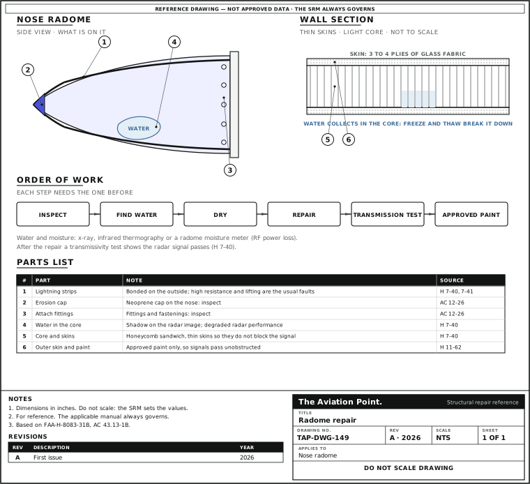
What a radome is, and what it carries
An electronic window. Radomes are often made of non-conducting honeycomb sandwich with only three or four plies of fiberglass; the skins are thin so that they do not block the radar signals (H p. 7-40). The fiber is glass, which transmits radio frequency and does not conduct, or sometimes quartz (DOT/FAA/TC-21/35, App. E).
What is on it. Attach fittings and fastenings, neoprene erosion caps and, where fitted, lightning strips (AC 12-26). The strips are bonded to the outside to dissipate the energy of a strike (H p. 7-40); many radomes have grounding strips to lead strikes and static away from the dome (H p. 11-62). Plastic-faced parts such as radomes are finished mainly against rain erosion (AC 3-11).
Why it is exposed. The thin structure in front of the aircraft makes it vulnerable to hail, bird strikes and lightning (H p. 7-40), and erosion by hail, rain, wind or blowing sand wears radomes and antennas (T.O. 1-1A-1, 2.1.10).
Identification. The part number, the class, the plies and the repair limits are on the radome's data plate and in its repair manual, not on this page. Do not identify a radome by looks.
What changes compared with structure
| Item | Structure | Radome |
|---|---|---|
| What the repair must preserve | Strength, weight and stiffness | The strength and the electrical properties: materials must preserve both (AC 3-1a) |
| The skin | As thick as the load needs | Thin on purpose, three or four plies, so it does not block the signal (H p. 7-40) |
| Water in the core | Dried before repair: it boils in the cure and disbonds the skin | A radar fault as well: it can shade the radar image and severely degrade the radar (H p. 7-40) |
| Paint | Corrosion and appearance | Approved paint only, so signals pass unobstructed (H p. 11-62) |
| Lightning | A conductive layer or the metal skin carries it away | Strips on the outside and fittings carry it; strips in poor condition endanger the radome (H p. 7-41) |
| Ordinary fiberglass repairs | Available for fairings, covers and cowlings | The AC says those fiberglass repairs are not to be used on radomes (AC 3-2 note) |
| Proof after the repair | Inspection, tap, balance on a control | A transmissivity test, so the signal passes (H p. 7-40) |
FAA-H-8083-31B pp. 7-40, 7-41 and 11-62; AC 43.13-1B pars 3-1, 3-2 and 3-11.
2Allowable damage
Inspecting a radome
Visual first. Look over the surface for damage, holes, cracks, chipping and peeling paint. Inspect the attach fittings and fastenings, the neoprene erosion caps and the lightning strips where fitted (AC 12-26).
Strips. Typical failures found at inspection are high resistance, caused by shorts in the strips or the attaching hardware, and strips lifting from the surface (H p. 7-41).
Water. Impact damage or erosion often lets water into the structure; it collects in the core and freezes and thaws each flight, which breaks the honeycomb down and leaves a soft spot on the radome (H p. 7-40). To detect water the handbook lists x-ray radiography, infrared thermography and a radome moisture meter, which measures the RF power lost to water (H p. 7-40). Which of these methods the radome manual allows is the manual's call.
Low-impact damage can leave disbonds and delaminations that show little on the surface (H p. 7-40). See damage assessment for the methods.
What you find, and what to do
| Finding | What the sources say | Source |
|---|---|---|
| Water in the core, soft spot | Repair quickly to avoid further damage and signal obstruction; dry before repair | H 7-40 |
| Disbond or delamination after a low-impact hit | Repair like other honeycomb sandwich, mindful that a repair can change the radar performance | H 7-40 |
| Holes, cracks, chipping, peeling paint | Found on the visual check; repair to the radome manual | AC 12-26 |
| Strip with high resistance or lifting | Repair the strip or its hardware: a strip in poor condition risks damage to the radome | H 7-41 |
| Erosion cap or fitting damaged | Inspect and replace as the manual says | AC 12-26 |
| How big a damage can stay, how many repairs are allowed | —: the radome manual sets the limit; no generic figure is published | SRM |
The public sources do not grade radome damage. Size limits, repair classes and the number of repairs allowed are in the radome maker's manual.
3Repair
Repairing a radome
Like honeycomb, with the signal in mind. The handbook says radome repairs are similar to repairs of other honeycomb structure, but the technician must realize they can affect radar performance, and that a special tool is needed for a severely damaged radome (H p. 7-40, Fig. 7-68). The method, the cutting of skin and core, the plug and the facing follow the sandwich repair guide.
Materials. They must preserve the strength and the electrical properties of the original, best done by replacing like with the same chemical composition or a substitute the manufacturer approves (AC 3-1a). Plies, fabric, resin, adhesive, filler and any added layer are as the radome manual says; a thicker or different wall changes the signal.
Dry the part first. Water in the core boils in the cure and leaves the skin disbonded; see the drying guide. A radome with free water is not repaired until it has been dried and checked.
Sealing and finish. Edges not protected by a bonded laminate are sealed to reduce moisture absorption (AC 3-11). The radome is painted only with approved paint, so signals pass unobstructed (H p. 11-62), and the finish is mainly against rain erosion (AC 3-11). Lightning strips and their hardware go back as they were.
Test. After the repair, a transmissivity test shows that the radar signal is transmitted properly through the radome (H p. 7-40), and the strips are checked for resistance and attachment (H p. 7-41).
Order of work
| Step | What it covers | Source |
|---|---|---|
| 1 Inspect | Surface, fittings, erosion caps, strips | AC 12-26 |
| 2 Find water | X-ray, infrared thermography or radome moisture meter | H 7-40 |
| 3 Dry | Part dried before any repair; the drying schedule is the SRM's | H-31B pp. 7-14, 7-35 |
| 4 Repair | Honeycomb repair with the radome's own materials; special tool if badly damaged | H 7-40; AC 3-1a |
| 5 Transmission test | Signal passes properly through the radome | H 7-40 |
| 6 Finish | Edges sealed; approved paint only | AC 3-11; H 11-62 |
| 7 Strips and records | Strips checked for resistance and lift; repair, materials, test results recorded | H 7-41 |
The drying schedule, the transmission test limits and the paint system are in the radome manual.
Worked example: a nose radome after a bird strike
A made-up case. A fiberglass nose radome has a 3 in (75 mm) crack and soft area near the tip after a bird strike, and the weather radar shows a shadow in that sector.
- Inspect: crack, peeling paint, erosion cap loose; strips intact on the visual check (AC 12-26).
- Water: a moisture meter or thermography over the soft area finds water in the core. That explains the radar shadow (H p. 7-40).
- Decide: check the radome manual for the size limit and repair class. This page gives none, because none is published.
- Dry, then repair: dry the part; cut out and replace the core and the facings with the manual's materials and ply count (AC 3-1a).
- Finish: seal the edges, refit the cap, paint with the approved system only (AC 3-11; H p. 11-62).
- Prove it: transmissivity test (H p. 7-40), strip resistance and lift check (H p. 7-41), then record.
Dry first, repair with the radome's own materials, test transmission, paint with approved paint only, and check the strips.
Cross-check against other documents
| Point | Document | What it says | Reading |
|---|---|---|---|
| Erosion of radomes | T.O. 1-1A-1 / NAVAIR 01-1A-1, para. 2.1.10; EASA AMC 20-29, para. 6.e | Both name erosion of antennas and radomes and erosion of composite structure as a degradation to protect against | The coating system in the repair data governs. |
| Diverting a strike | 14 CFR 25.581(c) | Non-metallic components comply by minimizing the effect of a strike or by providing acceptable means of diverting the current | A radome repair must keep the diverter strips (Handbook pp. 7-40, 7-41). |
| Surface layers | EASA AMC 20-29, para. 10.b(3) | The layers protecting against ultraviolet exposure and structural temperature must be properly repaired | Do not repaint a radome with a coating outside the approved list. |
Questions people actually ask
Can I use an ordinary fiberglass repair on a radome?
The AC says its fiberglass laminate repairs are not to be used on radomes. Use the radome manual's method and materials.
Why does a little water matter?
It collects in the core, freezes and thaws every flight and breaks the honeycomb down, and it can put a shadow on the radar image and degrade the radar (FAA-H-8083-31B p. 7-40).
Can I paint it with any paint?
No. Only approved paint, so that the radio signals pass unobstructed (FAA-H-8083-31B p. 11-62).
What is the allowable repair size?
No generic figure is published. The radome manual gives it, with the repair class.
Limits of this guide
What the sources support, and no further.
- The manual governs. Plies, thickness, materials, drying, paint system, damage size and test limits come from the radome maker's manual.
- No electrical figures. The public sources give no transmission-loss, boresight or paint-thickness limit, and this page lists none.
- Not covered. Antenna and radar-system tests, radome painting procedures, and radomes made of other materials.
Where to buy
Are you a distributor? Get listed →
Distributors coming soon.
Keep going
Calculators
Guides
Data sheets
Books

Buy
Distributors coming soon.
Main sources
- FAA-H-8083-31B, Aviation Maintenance Technician Handbook: Airframe, Chapter 7 — pp. 7-40 and 7-41, radome repairs, moisture detection, transmissivity test, lightning strips; p. 11-62, approved paint and grounding strips.
- AC 43.13-1B, Change 1, Acceptable Methods, Techniques, and Practices: Aircraft Inspection and Repair — Paragraphs 3-1a, materials that preserve electrical properties; 3-2 note, fiberglass repairs not for radomes; 3-11, finishing and sealing; 12-26, radome inspection.
- FAA Composite Structural Engineering Technology Safety Awareness Course, DOT/FAA/TC-21/35 (March 2022) — Appendix E, fiber types: glass and quartz for radomes.
- T.O. 1-1A-1 / NAVAIR 01-1A-1, Engineering Handbook Series for Aircraft Repair: Structural Hardware and Composites — Para. 2.1.10, erosion of antennas and radomes; reference list naming T.O. 1-1-24 and TM 01-1A-22 for radomes.
- EASA AMC 20-29, Composite Aircraft Structure (Annex II to ED Decision 2010/003/R, effective 26 July 2010) — Para. 6.e, protection of structure; para. 10.b(3), repair.
- 14 CFR 25.581, Lightning protection — Paragraph (c), non-metallic components.
Cross-checked with other manuals and standards in our library.