1Identification
Where to buyNumbers at a glance
| Item | Value, in (mm) | Source |
|---|---|---|
| Grain slope, maximum (all species of Table 1-1) | 1 in 15 | AC Table 1-1 col. 3; H Fig. 6-10 |
| Hard knot, sound, center third of the beam | 3/8 in (9.5) max; over 1/4 in (6.4) with caution | AC Table 1-1 note 1c |
| Distance between 3/8 in knots or other defects | 20 in (508) min | AC Table 1-1 note 1c(3) |
| Pitch pocket, center of the beam | 1-1/2 × 1/8 × 1/8 in (38 × 3.2 × 3.2) max, 14 in (356) apart in one ring | AC Table 1-1 note 1e |
| Moisture content at inspection | 8 to 16 %, preferably 10 to 12 % | AC 1-29 g |
| Moisture that sustains fungus | 20 % or more | AC 1-28 a, 1-29 g; H |
| Moisture before bonding | 6 to 8 % in arid regions, 10 to 12 % elsewhere | AC 1-44 b |
| Repair stock from another climate, seasoning | 2 weeks min, in the same storage area as the part | AC 1-44 b |
| Clamping pressure, resorcinol (typical) | 125 to 150 psi (0.86 to 1.03 MPa) softwood; 150 to 200 psi (1.03 to 1.38 MPa) hardwood | AC 1-10 b |
| Glue line, close-contact adhesive | 0.005 in (0.13) max | H, Glues |
| Bonding temperature | Above 70 °F (21 °C); the adhesive's minimum governs | H, Glues; AC 1-9 |
| Nail strips: pitch, row spacing, stagger, penetration | 1 in (25) apart, rows 1/2 in (13), no nail over 3/4 in (19) from the nearest, 3/8 in (9.5) into the lower member | AC 1-11 c |
| Clamping block thickness | 2 × the thinner member, min | AC 1-11 e |
| Scarf slope, plywood skin | 1 in 12 at the steepest | AC 1-51 c; H, Scarf Patch |
| Scarf slope, stressed solid member (spar) | Not steeper than 1 in 15 | H, scarf joints, Fig. 6-18 |
| Reinforcement plate ends | Feathered at 5 : 1 | AC Figs. 1-5 to 1-7; H Fig. 6-23 |
| Spacing between splices, or splice and plate | 3 × the longer splice, min | AC 1-40 |
| Drain holes in a repaired portion | Same as the originals, usually 1/4 in (6.4) | AC 1-37 |
| Heated bending form for plywood | 300 °F (149 °C) max surface | AC 1-49 b |
AC = AC 43.13-1B; H = FAA-H-8083-31B chapter 6. The manufacturer's data governs where it gives a value.
Species and permitted substitutes
| Species | Strength against spruce | Grain slope | As a substitute for spruce |
|---|---|---|---|
| Spruce: Sitka (P. sitchensis), red, white | 100 % (the standard) | 1 in 15 | Excellent for all uses |
| Douglas fir | Exceeds spruce | 1 in 15 | Same or slightly reduced sizes if the reduction is substantiated; splits and splinters; avoid large solid pieces (hard to inspect) |
| Noble fir | Slightly exceeds, but 8 % deficient in shear | 1 in 15 | Direct substitute in the same sizes if shear is not critical |
| Western hemlock | Slightly exceeds | 1 in 15 | Direct substitute; upland growth better than lowland |
| Northern white pine | 85 to 96 % | 1 in 15 | Only with larger sizes to make up the strength |
| Port Orford white cedar | Exceeds spruce | 1 in 15 | Same or slightly reduced sizes if substantiated; gluing difficult |
| Yellow poplar | Slightly less, except in compression and shear | 1 in 15 | Not a direct substitute without accounting for the lower strength |
AC 43.13-1B Table 1-1; FAA-H-8083-31B Fig. 6-10. Use the original species whenever possible (AC 1-2 b). Modified woods and non-wood products need the airframe manufacturer's or the FAA's approval for a substitute. The Handbook asks for traceability to MIL-S-6073 (solid spruce) and MIL-P-6070B (plywood) on certificated aircraft (H, Suitable Wood).
Adhesives: what AC 43.13-1B says about each
| Adhesive | Status | What to know | Source |
|---|---|---|---|
| Resorcinol-formaldehyde (two parts, resin and hardener) | ALLOWED | The only adhesive the AC names as recommended and approved for wood structure (Fed. Spec. MMM-A-181D, MIL-A-22397). Thin, uniform bond line and correct pressure are critical; full strength not relied on below 70 °F (21 °C) | AC 1-4 b(4); H, Glues |
| Epoxy (two parts) | ONLY WITH APPROVAL | Acceptable when it meets par. 1-4 a (aircraft manual, Mil Spec, AMS or TSO) and is compatible. Less sensitive to fit and pressure, but durability with heat or moisture is inadequate in many. Never change the mix ratio | AC 1-4 a, 1-4 b(6) |
| Casein | CHECK | Deteriorates with moisture and temperature; inferior to modern adhesives. Scrape off every trace before bonding with another type: residual alkalinity can stop the new adhesive curing | AC 1-4 b(1) |
| Plastic resin (urea-formaldehyde) | NOT ALLOWED | Obsolete for all repairs: deteriorates faster than wood in hot, moist service and under swell-shrink cycles. Any proposed use goes to the FAA first | AC 1-4 b(3) |
| Phenol-formaldehyde (hot pressed) | NOT ALLOWED | Used to make aircraft plywood; cured under heat and pressure, not practical for structural repair | AC 1-4 b(5) |
Pot life, open and closed assembly time, temperature and pressure: the adhesive maker's instructions (AC 1-8, 1-9). If an assembly time is exceeded, do not continue the bond (AC 1-8 note).
2Allowable damage
Defects in the stock: accept or reject
| Defect | How to recognize it | Decision | Source |
|---|---|---|---|
| Cross grain (spiral, diagonal) | Check all four faces. Slope is the number of units in which the grain deviates one unit; a scribe drawn along the grain or a drop of free-flowing ink shows the direction | ALLOWED to 1 in 15; steeper: reject | AC Table 1-1 note 1a, 2a; ANC-19 sec. 2.302 |
| Wavy, curly, interlocked grain | Local irregularities in the grain line | ALLOWED if within the cross-grain limit | AC note 1b, 2b |
| Hard knots | Sound, hard knots | ALLOWED to 3/8 in (9.5 mm) in the center third, 20 in (508 mm) from another defect, not on I-beam projections or flange edges; otherwise reject | AC note 1c, 2c |
| Pin knot clusters | Small clusters of tiny knots | ALLOWED if the effect on grain is small | AC note 1d, 2d |
| Spike knots | Knot running through the depth of a beam, across the rings; mostly in quarter-sawn stock | NOT ALLOWED | AC note 2e |
| Pitch pockets | Resin-filled openings along a ring | ALLOWED within the note 1e size and spacing; otherwise reject | AC note 1e, 2f |
| Mineral streaks | Dark streaks | ALLOWED only if close inspection shows no decay | AC note 1f, 2g |
| Checks, shakes, splits | Check: longitudinal crack across the rings. Shake: between two rings. Split: from induced stress | NOT ALLOWED | AC note 2h; ANC-19 sec. 2.303 |
| Compression wood | High specific gravity, excessive summerwood, little color contrast between spring and summer wood; formed on the lower side of leaning softwood trees, wide rings; in a thin section the summerwood looks opaque against a bright light | NOT ALLOWED; in doubt, reject or toughness test | AC note 2i; ANC-19 sec. 2.306 |
| Compression failures | Buckled fibers: streaks roughly at right angles to the grain, from pronounced to hairline | NOT ALLOWED if obvious; in doubt, microscope or toughness test | AC note 2j |
| Decay (rot, dote, red heart, purple heart) | Stains and discoloration that are not harmless | NOT ALLOWED in any piece | AC note 2k; H, Defects Not Permitted |
Selecting and approving wood stock is a specialized skill (AC 1-2 a); the AC refers to ANC-19 for aircraft-quality wood.
Damage in service and where it hides
Five failure modes. Decay (fungi need about 20 percent moisture or more); splitting, typically where a plywood doubler restrains a spruce member that shrinks as it dries; bond failure, from poor fabrication or long exposure to moisture; finish failure, the last barrier against water; and mechanical damage, including wood crushed under an overtightened fitting (AC 43.13-1B par. 1-28).
Where to look first. Spars at the ends of the plywood reinforcement plates at the lift-strut fittings, for compression and longitudinal cracks; rib attach points either side of the strut fittings; all metal fittings on wood, for looseness, corrosion and cracks; nose ribs and leading-edge skin ahead of the jury strut; exposed end grain, spar butts above all, which check in arid climates. Triple-check spars and spar-to-fuselage fittings after a wingtip strike or a ground loop (AC 1-29 f(2); H Fig. 6-8).
Signs under the covering. Swelling or warp; dark gray stains along the grain; fittings sunk into the wood; corroded screws or bolts, which mean moisture and probably decay next to them; splits in fabric over plywood, which call for removing the fabric and inspecting the plywood (AC 1-29 a, f(1), f(2)(j); H, External & Internal Inspection). A plate whose ends are not feathered is a stress riser where the primary structure can be expected to fail (AC 1-29 a).
Inspection methods and what each one finds
| Method | Sound result | Bad sign, and next step | Source |
|---|---|---|---|
| Moisture meter (probe through the skin if needed) | 8 to 16 %, best 10 to 12 % (AC); 8 to 12 % (H) | 20 % or more: fungus likely; dry the aircraft and inspect for decay | AC 1-29 g; H, Inspection of Wood Structures |
| Tapping with a light plastic hammer or screwdriver handle | Sharp, solid report | Hollow, soft: go on to probing | AC 1-29 b |
| Probing with a sharp tool | Solid and firm | Soft, mushy: assume rot; disassemble | AC 1-29 c |
| Prying at bond joints; feeler gauge at glue lines | No relative movement, no separation | Movement: bond failure; disassemble | AC 1-29 d; H Fig. 6-6 |
| Smell, when the panels come off | No odor | Musty or moldy: moisture and fungus | AC 1-29 e |
| Light at a low angle, parallel with the grain | Straight grain | Grain waviness: possible compression failure | AC 1-29 f(2)(m); H, Inspection of Wood Structures |
| Borescope or inspection holes (aft face of front spar, fore face of rear spar) | No cracks | Compression or longitudinal cracks, loose rib nails: investigate | AC 1-29 f(2)(m) |
| Removing a few screws or bolts | Bright fasteners | Corrosion: moisture, probable decay nearby | AC 1-29 f(2)(j); H |
| Sample joint from the same batch, broken after cure | Wood fibers on both faces; at least 75 % wood failure (H) | Failure in or along the bond line: poor bonding | AC 1-29 h; H, Testing Glued Joints |
Keep the aircraft in a dry, ventilated hangar with all covers off as long as possible before the final inspection (AC 1-29). The manufacturer's inspection data is followed in all cases.
What may stay, what is repaired, what is replaced
| Finding | Decision | Source |
|---|---|---|
| Decay, any amount or form | NOT ALLOWED: repair or replace the wood | AC 1-28 a |
| Compression failure in a spar | NOT ALLOWED to stay; can lead to wing failure in flight; the manufacturer's data decides splice or replacement | AC 1-29 f(2)(k); H |
| Longitudinal crack in a solid or laminated spar (not a box spar) | ONLY WITH APPROVAL: bonded spruce or plywood plates both sides, well past the crack (Fig. 1-10). No procedure fits every model: the manufacturer, or the FAA when not per the manufacturer or the AC | AC 1-44, 1-44 b |
| Elongated bolt holes, cracks near bolt holes | Splice in a new section or replace the spar. Minimal damage at non-critical fittings: repair ONLY WITH APPROVAL (manufacturer or FAA) | AC 1-45 |
| Bond line moves or opens | NOT ALLOWED: disassemble, clean and rebond | AC 1-29 d |
| Slight bulging between panels of single plywood covering | CHECK: may be permissible if wood and glue are sound; check the attachment to the structure | H, External & Internal Inspection |
| Hole in plywood skin up to 1 in (25 mm), 1 in from any frame, not on a leading edge or the fuselage front | ALLOWED: doped fabric patch | AC 1-52 |
| Plywood stressed covering damaged over 6 in (152 mm) in any direction | Repair is a MAJOR REPAIR: FAA Form 337 | 14 CFR 43 App. A (b)(1)(xxii) |
| Crack length, decay depth or damage size that may remain | —: the manufacturer's data sets it; the public documents give no generic limit | AC 1-36, 1-44 b |
3Repair
Rules every wood repair follows
The standard. As strong as the original and equivalent in rigidity and aerodynamic shape; the manufacturer's specifications whenever they exist (AC 43.13-1B par. 1-36). Inspect the internal structure next to any skin damage and repair frame members first (par. 1-47).
Major repairs. Spars, spar flanges, wing main ribs and compression members, three or more adjacent ribs, and plywood stressed covering over 6 in in any direction (14 CFR 43 App. A (b)(1)(iv), (v), (x), (xxii), (xxv)). Replacing a spar is a major repair; new spars come from the manufacturer or a PMA holder, or are made from a manufacturer-approved drawing or a verified original (AC 1-41).
Control surfaces. No weight added aft of the hinge line; stiffness, weight distribution and mass balance as original; check the balance as the aircraft manual says (AC 1-38). Changes that affect flutter are major alterations (14 CFR 43 App. A (a)(1)(xiii)).
Bond faces. Machined smooth and true, bonded soon after surfacing, free of oil, wax, finish, dope and old adhesive. Never sandpaper a softwood bond face; on plywood or aged faces that cannot be re-machined, a very light 220-grit sanding is allowed. A water drop that will not spread shows a surface that will not bond (AC 1-6, 1-6 a, 1-6 b). Adhesive on both faces (1-7).
Spar splices and spar repairs
| Point | Rule | Source |
|---|---|---|
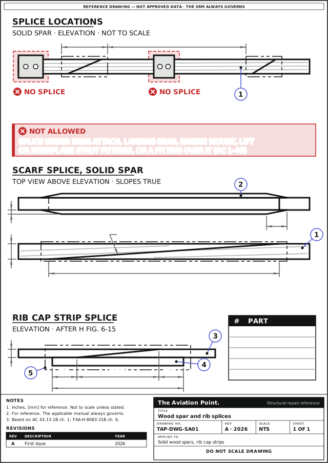
| Where a spar may be spliced | Anywhere except under wing attachment, landing gear, engine mount, or lift and interplane strut fittings; those fittings may not overlap the splice | AC 1-40; H, Wing Spar Repairs |
| Under minor fittings (drag and antidrag wire, compression strut) | Acceptable if the plates do not disturb the fitting, pulley or bellcrank brackets; plates on the rear face of the rear spar or front face of the front spar, with longer bolts | AC 1-40 a, b |
| Distance from another splice or a reinforcing plate | Not adjacent; at least 3 × the length of the longer splice | AC 1-40 |
| Number of splices | Not more than two in any one spar | H, Wing Spar Repairs |
| Scarf slope | Not steeper than 1 in 15 in a stressed part such as a spar; the slopes in AC Figs. 1-5 to 1-9 are minimum slopes | H, scarf joints, Fig. 6-18; AC 1-40 |
| Grain next to the scarf | Cut along the general grain slope. No deviation steeper than 1 in 15 in an outer eighth of the spar depth; steeper local slope only in the inner quarter of a flange | AC 1-39, Fig. 1-4; H Fig. 6-18 |
| Reinforcement plates | Required on every scarf repair to a spar; spruce or plywood, bonded only, ends feathered 5 : 1 | AC 1-40, Figs. 1-5 to 1-7; H Fig. 6-23 |
| Insert in the top or bottom of a solid spar | Insert of the same species; scarf at the ends of the insert no less than 12 to 1 | AC Fig. 1-10; H Fig. 6-27 |
| Box spar webs | Same type of plywood, face grain as the original; never solid wood for a plywood web | AC 1-42, Fig. 1-9 |
| Solid spar to laminated, or back | Allowed with material of the same high quality; external reinforcements replaced as original | AC 1-43 |
| Bolt holes | Sized so the bolt or bushing needs light tapping with a wood or rawhide mallet; seal the hole and let it cure before the bolt goes in; bushings slightly short | H, Bolt & Bushing Holes; AC 1-71, 1-2 c(1) |
| Moisture when bonding a cracked spar's plates | 6 to 8 % in arid areas, 10 to 12 % elsewhere; seal spar butts with a penetrating, moisture-resistant finish | AC 1-44 b, c |
Rib repairs
| Point | Rule | Source |
|---|---|---|
| Replacement rib | From the manufacturer or a PMA holder, or made from an approved drawing or a verified original rib; the contour matters for handling | AC 1-46 |
| Cap strip scarf splice | Scarf 10 × the cap thickness A; spruce block on the side away from the covering, 16 A long (3 A past each end of the scarf); plywood side plates both sides, same material and thickness as the rib's own | H, Wing Rib Repairs, Fig. 6-15; AC Fig. 1-11 |
| Rib to wood spar | Never nail through the cap strips. Adhesive plus cement-coated, barbed or spiral nails through the vertical rib members on each face of the spar | AC 1-46 a |
| Compression ribs | Methods of AC Fig. 1-12 (A), (B), (C): cut and replace the cap strips, bonded plywood side plates; on (B) and (C) the plates run the full distance between the spars | AC 1-46 b |
| Three or more adjacent ribs, or the leading edge between them | MAJOR REPAIR | 14 CFR 43 App. A (b)(1)(xxv) |
Spar and rib splices: where, how long, how steep
Plywood skin patches: which one, and its limits
| Patch | Use when | Key dimensions, in (mm) | Source |
|---|---|---|---|
| Fabric (doped on) | Hole up to 1 in (25) after trimming; not within 1 in (25) of a frame member; not on a leading edge or the fuselage front | Edges of the hole sealed; patch overlaps the skin 1 in (25) min, pinked edges | AC 1-52; H, Fabric Patch |
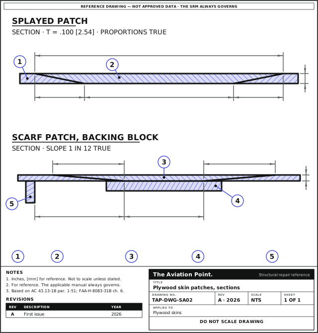
| Splayed (flush, tapered) | Hole up to 15 T, skin not over 1/10 in (2.5) | Taper 5 T (5 : 1); 1/10 in skin: hole 1-1/2 in (38) max, repair circle 2-1/2 in (64) | AC 1-51 a; H, Splayed Patch |
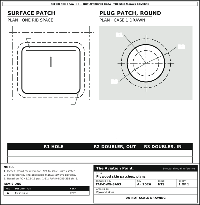
| Surface (overlay) | Between or along framing members, entirely aft of the 10 % chord line or wrapped round the leading edge to end aft of it. The Handbook limits it to skins not over 1/8 in (3.2) | Perimeter up to 50 in (1,270), one frame or rib space; corner radius 5 T min; forward edge bevel 4 T; fabric over it lapping 2 in (51); H: doublers 1/4 in (6.4) min | AC 1-51 b; H, Surface Patch |
| Scarf (the preferred repair) | Radius of curvature over 100 T at every point of the trimmed opening | Slope 1 in 12 at the steepest; backing-block method for damage up to 25 T across and 15 T or more from a framing member | AC 1-51 c, Figs. 1-15, 1-16; H, Scarf Patch |
| Plug, round or oval | Skin damage only, structure underneath sound | Round: hole radius 2 in (51) or 3 in (76); doubler radius 2-5/8 and 1-3/8 in (67 and 35), or 3-7/8 and 2-1/8 in (98 and 54). Oval: 7 × 5 in (178 × 127) max. Doubler 1/4 in (6.4) soft plywood, preformed when the rise exceeds 1/8 in in 6 in (3.2 in 152); No. 4 round-head screws | AC 1-51 d, Figs. 1-17, 1-18; H, Plug Patch |
T = skin thickness. Face grain of every patch as the original skin. A patch on plywood stressed covering over 6 in (152 mm) is a major repair (14 CFR 43 App. A (b)(1)(xxii)). The AC's other figure dimensions (scarf patch backing, gussets) are in Figs. 1-15 and 1-16.
Splayed and scarf patches in section
Surface and plug patches in plan
Minimum bend radius for aircraft plywood
| Thickness | Plies | Cold mandrel, 90° to face grain, in (mm) | Cold, 0° or 45° | Soaked in hot water, 90° | Soaked, 0° or 45° |
|---|---|---|---|---|---|
| .035 in (0.9) | 3 | 2 (51) | 1.1 (28) | 0.5 (13) | 0.1 (2.5) |
| .070 in (1.8) | 3 | 5.2 (132) | 3.2 (81) | 1.5 (38) | 0.4 (10) |
| .100 in (2.5) | 3 | 8.6 (218) | 5.2 (132) | 2.6 (66) | 0.8 (20) |
| .125 in (3.2) | 3 | 12 (305) | 7.1 (180) | 3.8 (97) | 1.2 (30) |
| .155 in (3.9) | 3 | 16 (406) | 10 (254) | 5.3 (135) | 1.8 (46) |
| .185 in (4.7) | 3 | 20 (508) | 13 (330) | 7.1 (180) | 2.6 (66) |
| .160 in (4.1) | 5 | 17 (432) | 11 (279) | 6 (152) | 2 (51) |
| .190 in (4.8) | 5 | 21 (533) | 14 (356) | 7 (178) | 3 (76) |
| .225 in (5.7) | 5 | 27 (686) | 17 (432) | 10 (254) | 4 (102) |
| .250 in (6.3) | 5 | 31 (787) | 20 (508) | 12 (305) | 5 (127) |
| .315 in (8.0) | 5 | 43 (1,092) | 28 (711) | 16 (406) | 7 (178) |
| .375 in (9.5) | 5 | 54 (1,372) | 36 (914) | 21 (533) | 10 (254) |
AC 43.13-1B Table 1-2: cold columns at 10 % moisture content; soaked columns thoroughly soaked in hot water, then bent on cold mandrels. Dry the part on the form; a heated form may reach 300 °F (149 °C) (AC 1-49). Double curvature needs molded plywood of the right shape (AC 1-50); a sheet of heavy paper that wrinkles on the surface shows double curvature (AC 1-48).
Step by step: a bonded wood repair
| Step | Action | What to do |
|---|---|---|
| 1 | Get the data | The manufacturer's repair data first; AC 43.13-1B chapter 1 where none exists. Check whether the repair is major (14 CFR 43 App. A). |
| 2 | Dry and inspect | Moisture meter, tap, probe and look; dry the structure before judging bonds (AC 1-29). |
| 3 | Cut back to sound wood | Remove all decay and damage; lay out the scarf or patch with the slopes and sizes in the tables above. |
| 4 | Prepare the faces | Machine smooth and true; vacuum; no sandpaper on softwood bond faces; keep sealer off the bond areas plus 1/4 in (6.4 mm) (AC 1-6, 1-66 d). |
| 5 | Mix and spread | Within pot life; adhesive on both faces; never thin a batch to extend its life (AC 1-7, 1-8). |
| 6 | Clamp | Pressure per the adhesive, evenly, with blocks at least twice the thinner member; nail strips at 1 in (25 mm) pitch. Check squeeze-out along the whole joint and wipe the excess (AC 1-10, 1-11). |
| 7 | Test a sample | A joint from the same batch and the repair's scraps, broken after cure: wood failure on both faces (AC 1-29 h). |
| 8 | Finish and record | Seal, varnish and refinish; drain holes as original; logbook entry, and FAA Form 337 for a major repair. |
Finishing and protection
| Surface | Finish | Source |
|---|---|---|
| Acceptable finishes | Varnish to Fed. Spec. TT-V-109, or a coating approved by the airframe manufacturer or the FAA; STC exterior systems made under PMA; low-viscosity epoxy as an inside finish where bonding follows | AC 1-65 |
| Interior members, inside of skins, box spars | One thinned coat, then two full coats; wheel wells and hull bottoms: an extra coat of aluminised sealer, 12 to 16 oz of aluminum paste per gallon (90 to 120 g/L) | AC 1-67 |
| End grain (spar butts, skin edges, holes, scarfed faces) | One thinned coat, then 2 to 4 full coats to a smooth gloss; under dope or lacquer, a dope-proof sealer or epoxy | AC 1-69 |
| Bond areas | Keep sealer off them plus 1/4 in (6.4 mm) each side; seal the margins after cure, or use an approved epoxy coating with a compatible epoxy adhesive | AC 1-66 d, e |
| Plywood under fabric or tape (dope system) | Dope-proof one-part varnish or two-part epoxy varnish, two clear dope coats, a third with pinked airplane cloth laid in it, then brush and spray coats | AC 1-70, 2-6 g |
| Bolt holes | Varnish or sealer into the hole, fully cured before the bolt | AC 1-71; H |
| Color | A dark aircraft in the sun can reach 185 °F (85 °C) inside; wood loses about 25 % of its strength at 125 °F (52 °C). White or light colors run coolest | AC 1-68 |
| Before finishing | Remove adhesive squeeze-out, oil (naphtha), wax crayon marks, sawdust and chips from closed bays | AC 1-66 a to c |
Worked example: a hole in 1/10 in plywood skin
Wing skin T = 0.100 in (2.5 mm), damage trimmed round to 2 in (51 mm), radius of curvature 20 in (508 mm), back of the skin reachable. A made-up case to show the AC 43.13-1B par. 1-51 arithmetic.
- Fabric patch? Only up to 1 in (25 mm): no (par. 1-52).
- Splayed patch? Largest hole 15 T = 15 × 0.100 = 1.5 in (38 mm): the 2 in hole is too big (par. 1-51 a).
- Scarf patch: curvature check 100 T = 10 in (254 mm); 20 in is above it, so a scarf patch may be installed (par. 1-51 c).
- Scarf width at 1 in 12: 12 T = 1.2 in (30 mm) each side; outside diameter of the scarf 2 + 2 × 1.2 = 4.4 in (112 mm).
- Backing-block method (Fig. 1-15, section D-D): damage up to 25 T = 2.5 in (64 mm) across and at least 15 T = 1.5 in (38 mm) from a framing member. The 2 in hole qualifies if its edge is 1.5 in or more from the frame.
- Paperwork: 2 in is under the 6 in (152 mm) of 14 CFR 43 App. A (b)(1)(xxii), so the skin damage alone does not make it a major repair.
A scarf patch, 4.4 in (112 mm) across at 1 in 12, on a backing block if the hole is 1.5 in (38 mm) clear of framing; face grain as the skin.
Cross-check against other documents
| Point | Document | What it says | Reading |
|---|---|---|---|
| Moisture at inspection | AC 1-29 g; H, Inspection of Wood Structures | AC: 8 to 16 %, preferably 10 to 12 %. H: ideal 8 to 12 %. Both: over 20 % means fungus | Agree on 20 %; aim for 10 to 12 %. |
| Moisture before bonding | AC 1-44 b; H, Glues | AC: 6 to 8 % in arid areas, 10 to 12 % elsewhere. H: 8 to 12 %, equal in both parts | Match the climate the aircraft lives in; both parts the same. |
| Clamping pressure | AC 1-10 b; H, Glues, Fig. 6-12 | AC (resorcinol, typical): 125 to 150 psi softwood, 150 to 200 psi hardwood. H: 10 to 150 psi softwood by glue viscosity, up to 200 psi hardwood; example 100 to 250 psi at 75 °F | Differ: the adhesive maker's sheet governs, as both say. |
| Scarf slope in a spar | H, scarf joints, Figs. 6-18, 6-24; AC 1-40 | H: not steeper than 15 to 1 in a stressed part; Fig. 6-24 shows 10 to 1 in solid wood. AC: the figure slopes are minimum slopes | Use the flatter of the manufacturer's slope and 1 in 15 on a spar. |
| Scarf patch on a curved skin | AC 1-51 c; H, Scarf Patch | AC: radius over 100 T at all points. H prints «not greater than 100 times» | The H wording is reversed; the AC governs: a flatter skin takes a scarf patch. |
| Surface patch skin thickness | AC 1-51 b; H, Surface Patch | AC gives no thickness limit; H: skins not over 1/8 in | Apply the 1/8 in limit (stricter). |
| Splices in one spar | AC 1-40; H, Wing Spar Repairs | AC: spacing 3 × the longer splice. H: not more than two splices | Both apply. |
| Test joint acceptance | AC 1-29 h; H, Testing Glued Joints | AC: wood fibers on both faces is the ideal. H: at least 75 % wood fiber over the fracture | Use 75 % as the figure. |
| Size of a skin repair and paperwork | AC 1-51 b; 14 CFR 43 App. A (b)(1)(xxii) | AC allows a surface patch up to 50 in perimeter. The rule: plywood stressed covering over 6 in in any direction is a major repair | A large AC patch is still a major repair: Form 337. |
| Compression wood | AC Table 1-1 note 2i; ANC-19 sec. 2.306 | AC: high specific gravity, excessive summerwood, low color contrast. ANC-19: lower side of leaning trees, wide rings, opaque summerwood in thin section | Agree: reject it; in doubt, toughness test. |
Quick check
Plywood skin 0.100 in thick, hole trimmed round to 1-3/4 in, clear of framing, radius of curvature 20 in. Which patch does AC 43.13-1B par. 1-51 allow?
- A splayed patch
Not this one. No: a splayed patch takes holes up to 15 T = 1.5 in.
- A scarf patch at 1 in 12
Best fit. Yes: the radius is over 100 T = 10 in, and the scarf patch is the preferred skin repair.
- A doped fabric patch
Not this one. No: fabric patches are for holes up to 1 in.
On a real job, the SRM decides.
Questions people actually ask
Can I replace spruce with Douglas fir?
Yes, in the same or slightly reduced sizes if the reduction is substantiated. It is hard to work with hand tools and splits; avoid large solid pieces, which are hard to inspect (AC 43.13-1B Table 1-1). Use the original species whenever possible (par. 1-2 b).
Is epoxy acceptable instead of resorcinol?
Only if it meets par. 1-4 a (aircraft manual, Mil Spec, AMS or TSO) and is compatible with the structure. Many epoxies lack durability with heat or moisture; never change the mix ratio to alter cure time (par. 1-4 b(6)).
Can I bond over old casein glue?
Scrape off every trace first: residual alkalinity can stop the new adhesive curing (par. 1-4 b(1)).
How do I find a compression failure?
Shine a light at a low angle along the grain on the compression face: waviness in the grain is the sign. A borescope through inspection holes, or new holes on the aft face of the front spar and fore face of the rear spar, lets you see the face and top of the spar (par. 1-29 f(2)(m); FAA-H-8083-31B ch. 6).
When is a wood repair a major repair?
Spars, spar flanges, wing main ribs and compression members, three or more adjacent ribs, and plywood stressed covering over 6 in in any direction (14 CFR 43 App. A (b)(1)). Spar replacement is a major repair (par. 1-41).
Why seal end grain so heavily?
End grain absorbs far more moisture than side grain: one thinned coat and two to four full coats (par. 1-69). Spar butts in dry climates check and split without it (par. 1-44 c).
Limits of this guide
What the sources support, and no further.
- The manufacturer's data governs spar, rib and skin repairs, splice locations and crack limits when it exists (AC 43.13-1B par. 1-36).
- No generic damage limit is published: any decay is repaired or replaced; crack and damage sizes that may remain are the manufacturer's.
- Figure dimensions of AC Figs. 1-5 to 1-12, 1-15 and 1-16 (plate lengths, gussets, backing strips) are not reproduced: read the figure.
- Adhesive times, temperatures and pressures come from the adhesive maker's data.
- Not covered: wood propellers, and the design of new wood structure.
Where to buy
Are you a distributor? Get listed →
Distributors coming soon.
Keep going
Calculators
Guides
Books
Buy
Distributors coming soon.
Main sources
- AC 43.13-1B with Change 1, Acceptable Methods, Techniques, and Practices: Aircraft Inspection and Repair — Chapter 1: par. 1-2 and Table 1-1 (species, defects); pars. 1-3 to 1-11 (plywood, adhesives, bonding); pars. 1-18, 1-19 (safety); pars. 1-28, 1-29 (deterioration, inspection); pars. 1-36 to 1-52 with Figs. 1-2 to 1-18 and Table 1-2 (repairs); pars. 1-64 to 1-71 (finishing). Chapter 2: par. 2-6 g (plywood under fabric).
- FAA-H-8083-31B, Aviation Maintenance Technician Handbook: Airframe, Volume 1, Chapter 6, Aircraft Wood and Structural Repair — Inspection of Wood Structures, Fig. 6-6 and 6-8; Suitable Wood, Defects and Fig. 6-10; Glues and Fig. 6-12; Testing Glued Joints; Wing Rib Repairs, Figs. 6-15, 6-18; Wing Spar Repairs, Figs. 6-23, 6-24, 6-27; Bolt & Bushing Holes; Plywood Skin Repairs (fabric, splayed, surface, plug and scarf patches).
- ANC-19, Wood Aircraft Inspection and Fabrication, Army-Navy-Civil Committee (20 December 1943) — Secs. 2.302 (slope of grain, scribe and ink), 2.303 (checks, shakes, splits) and 2.306 (compression wood).
- 14 CFR Part 43, Appendix A, Major Alterations, Major Repairs, and Preventive Maintenance — (a)(1)(xiii); (b)(1)(iv), (v), (x), (xxii) and (xxv).
Cross-checked with other manuals and standards in our library.