1Identification
Where to buyThe drawing
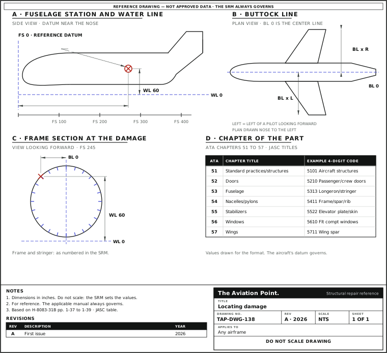
The location systems
| Mark | Name | Measured |
|---|---|---|
| FS | Fuselage station (some makers: body station, BS) | In inches from the reference datum, a vertical plane at or near the nose. Fore and aft, parallel to the center line from the nose through the tail cone |
| BL | Buttock line | From the vertical plane down the center of the aircraft, to the left or to the right |
| WL | Water line | Height in inches, perpendicular to a horizontal plane usually at the ground, the cabin floor or another easy reference |
| AS | Aileron station | Outboard from, and parallel to, the inboard edge of the aileron, perpendicular to the rear beam of the wing |
| KS | Flap station | Outboard from, and parallel to, the inboard edge of the flap, perpendicular to the rear beam |
| NC / Nac. Sta. | Nacelle station | Forward of or behind the front spar of the wing, perpendicular to a designated water line |
| HSS · VSS · PPS | Horizontal stabilizer, vertical stabilizer and powerplant stations | Used on large aircraft. The manufacturer's terminology and the station system apply in every case |
FAA-H-8083-31B pp. 1-37 to 1-38 and figs. 1-88 to 1-91. «Frame station 137» is a frame 137 inches behind the zero station.
The datum is the manufacturer's
The reference datum is wherever the manufacturer put it: the handbook says at or near the nose, and for the center line many manufacturers use zero with measurements left and right, often on the horizontal stabilizer and the wings. The numbering system and the abbreviations are not always the same from one maker to the next, so review them in the manual before locating a member.
Stations are measured from their own datum: a wing station off the butt line, a stabilizer station off the butt line, an engine nacelle station off the wing front spar. Always write the system with the number: «FS 245» and «WS 245» are two places.
Zones and panels
Large aircraft are divided into major zones, and each into sequentially numbered zones and subzones. The digits of a zone number are reserved and indexed to the location and to the system of the component. Panels and doors are numbered too: on large aircraft the number usually carries the zone and subzone, and left or right is shown by an «L» or «R», or by odd numbers on one side and even on the other.
Each manufacturer has its own panel numbering, explained in its maintenance manual with diagrams and tables of what is behind each panel. Locating the part and getting access to it are two jobs: the panel number tells you the second.
ATA chapters 51 to 57 and the JASC codes under them
| ATA | Chapter | JASC codes (four digits) |
|---|---|---|
| 51 | Standard practices / structures | 5100 standard practices and general procedures for typical repairs common to several chapters; 5101 aircraft structures, general reports touching two or more areas |
| 52 | Doors | 5210 passenger/crew · 5220 emergency exits · 5230 cargo/baggage · 5240 service doors (5241 to 5248) · 5250 fixed inner doors · 5260 entrance stairs · 5280 landing gear doors |
| 53 | Fuselage | 5311 frame · 5312 bulkhead · 5313 longeron/stringer · 5314 keel · 5315 floor beam · 5321 floor panel · 5330 plate/skin (with access covers) · 5340 attach fittings (5341 wing, 5342 stabilizer, 5343 landing gear, 5344 door hinge) · 5350 aerodynamic fairings |
| 54 | Nacelles / pylons | 5411 frame/spar/rib · 5412 bulkhead/firewall · 5413 longeron/stringer · 5414 plate/skin · 5415 attach fittings · 5420 miscellaneous structure |
| 55 | Stabilizers | 5511 stabilizer spar/rib · 5512 stabilizer plate/skin · 5521 and 5522 elevator spar/rib and plate/skin · 5531 and 5532 vertical stabilizer · 5533 ventral · 5541 and 5542 rudder · 5550 attach fittings |
| 56 | Windows | 5610 flight compartment · 5620 passenger compartment · 5630 door windows · 5640 inspection windows |
| 57 | Wings | 5711 spar · 5712 rib/bulkhead · 5713 longeron/stringer · 5714 center box · 5720 miscellaneous (tips, clips, brackets, doublers) · 5730 plate/skin · 5740 attach fittings · 5751 aileron (hinges and balance weights) · 5752 aileron tab · 5753 trailing edge flap · 5754 leading edge devices · 5755 spoilers |
FAA Joint Aircraft System/Component (JASC) Code Table and Definitions, Oct 2008. It is a modified version of ATA Specification 100: the first two digits are the ATA chapter, the fourth digit is the FAA's own. The SRM of the aircraft has its own sections under each chapter.
2Allowable damage
Where it is decides which limit applies
Where the damage is decides which limit applies. The same dent, scratch or crack is judged against the SRM entry of the component it is in, and often of the zone of that component. The source is blunt about it: negligible limits vary with structure, material and loading, and location is one of the five things that decide whether a repair is possible at all (FAA-H-8083-31B pp. 4-90 to 4-91: type of damage, original material, location, repair required, tools and equipment).
So the station, the buttock line and the water line are not paperwork. They are the key that finds the SRM figure, and the only way the next person finds the repair.
What the limits are written against
| Damage | Take | Limit |
|---|---|---|
| Scratch, nick, gouge | Depth against the section; length; the part it is in | The SRM, per part. An Alclad scratch that does not break the cladding is generally negligible |
| Dent | Depth and size; where it sits on the part; any sign of fasteners disturbed | The SRM, per part and zone |
| Crack | Length; where it starts (edge, hole, load point, change of section) | None is negligible until the damage limits of the structure are known |
| Hole | Size and shape; distance to the edges and to the supporting structure | The SRM |
| Corrosion | Extent and depth; the load on the part | Light, moderate or severe: the structural manual gives the class |
TO 1-1A-1 / NAVAIR 01-1A-1 Table 2-1. Write the position next to each measurement: the distance from the nearest frame, stringer or rib, and from the nearest fastener row.
3Repair
Writing the location into the record
| Step | Action | What to do |
|---|---|---|
| 1 | Name the system | State which station system the manual uses and that you read it from the manual of this aircraft. |
| 2 | Give the coordinates | FS, BL and WL of the center of the damage; for a repair, of its edges. Use the manual's abbreviations. |
| 3 | Name the member | The component, the bay between the frames or ribs, and the stringers or stiffeners, as the SRM numbers them. |
| 4 | Give the chapter | ATA chapter 51 to 57 and, if the report is a Service Difficulty Report, the four-digit JASC code of the part. |
| 5 | Point to the data | The SRM figure or task, or the approved data, that gave the limit and the repair. |
| 6 | Sign for it | The entry carries the description of the work or the data reference, the date, and the signature, certificate number and kind of certificate (14 CFR 43.9(a)). |
Worked example: placing a dent in the record
A dent in the left fuselage skin. The numbers are drawn for the format, as in the figure: the real ones are the aircraft's.
- Read the datum and the abbreviations in the aircraft's manual: FS from the reference datum, BL from the center line, WL from the manual's base plane.
- Find the bay: the dent lies between frames FS 237 and FS 253 and between two stringers numbered in the SRM. Center of the dent: FS 245, BL 50 L, WL 60.
- Component and chapter: fuselage plate/skin, ATA chapter 53, JASC 5330.
- Open the SRM at that skin and zone, and take the dent limit for that bay. Measure the dent against it.
- Write: left fuselage skin, bay FS 237 to FS 253, center FS 245 / BL 50 L / WL 60, chapter 53 (JASC 5330), SRM reference, result, signature.
The record can be found again by coordinates and by chapter, and the limit used is the limit of that zone.
Questions people actually ask
Is FS 0 always the nose?
No. The handbook says the datum is a vertical plane at or near the nose, and that numbering systems differ from one manufacturer to another. Use the datum of the aircraft's own manual.
Which chapter is a flap or aileron hinge?
The JASC code table splits the surface from its fitting: 5744 is wing control-surface attach fittings, 5751 ailerons includes the hinges and balance weights, 5753 is trailing edge flaps.
What is the JASC code used for?
The FAA built it as a modified ATA Specification 100 code to classify structures and systems in Service Difficulty Reports and accident or incident data. The first two digits read as the ATA chapter.
Which chapter holds the standard practices for structure?
Chapter 51. The JASC definition of 5100 is the standard practices and general procedures for typical repairs applicable to more than one chapter, not covered in chapters 52 to 57.
Limits of this guide
What the sources support, and no further.
- No limits are given here. Dent depths, crack lengths and zone limits are the SRM's.
- No aircraft datum is given. Station values in the figure and the example are drawn for the format.
- ATA chapters. The chapter numbers are those of ATA Specification 100 as modified in the FAA JASC table; the sections of each manual below chapter level belong to its manufacturer.
Where to buy
Are you a distributor? Get listed →
Distributors coming soon.
Keep going
Calculators
Guides
How to do it
Books
Main sources
- FAA-H-8083-31B, Aviation Maintenance Technician Handbook: Airframe, Chapter 1 — pp. 1-37 to 1-39: location numbering systems, zones, access and inspection panels; figs. 1-88 to 1-92. Chapter 4, pp. 4-90 to 4-91: what decides repairability.
- FAA Joint Aircraft System/Component (JASC) Code Table and Definitions, October 2008 — Chapters 51 to 57 and their four-digit codes and definitions; preface on ATA Specification 100.
- TO 1-1A-1 / NAVAIR 01-1A-1, Engineering Handbook Series for Aircraft Repair: General Manual for Structural Repair — Table 2-1, types of damage.
- 14 CFR 43.9(a) — Content of maintenance records.
Cross-checked with other manuals and standards in our library.