1Identification
Where to buyThe drawing
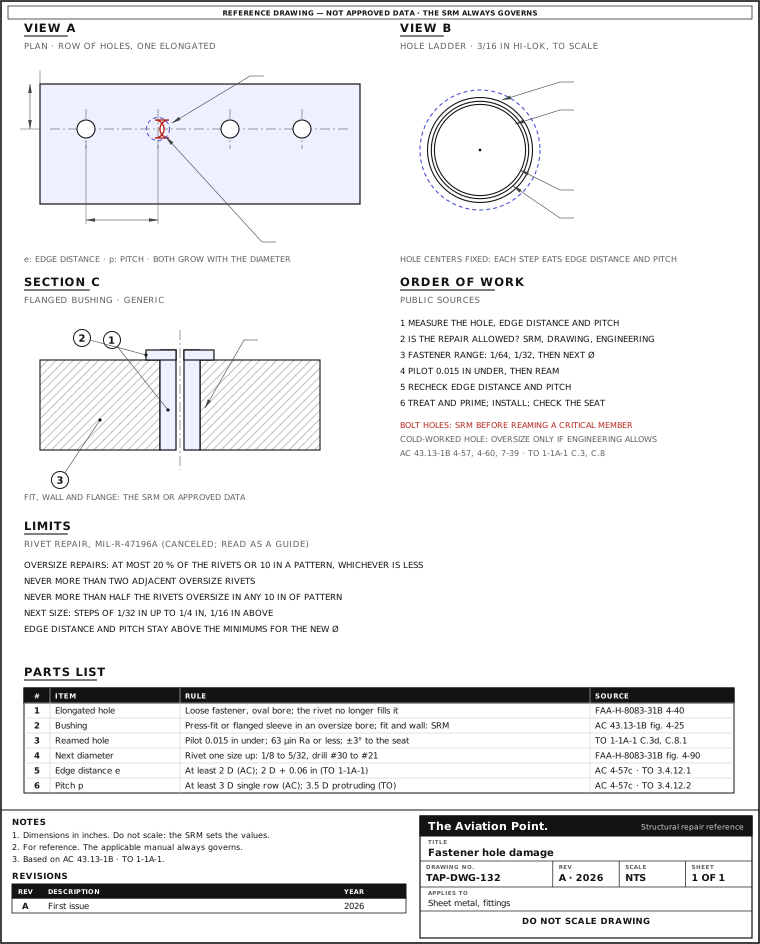
How a damaged hole shows
| Defect | How you find it | Where the rule sits |
|---|---|---|
| Elongated or oval hole | Sheared or popped fasteners, loose rivets, elongated holes and cracks at attachments; chipped or cracked paint round a fastener may mark a failure. Remove one or more rivets next to damaged structure and look | TO 1-1A-1 pars. 2.4.3, 2.4.4; AC 43.13-1B par. 4-52 |
| Hole too large for the fastener | A blind-rivet stem that moves under a 10 lb force on the trimmed stem: any looseness means an oversize hole | FAA-H-8083-31B p. 4-40 |
| Enlarged or distorted by removal | Chiseling a rivet head off probably distorts the hole and damages the skin; drilled-out holes can be enlarged | AC 43.13-1B par. 4-52; removing a rivet |
| Enlarged countersink | The head no longer sits flush; the countersink is beyond tolerance | MIL-R-47196A par. 3.4.2 |
| Scored or heat-marked wall | Tool marks at 45° or less to the hole axis; discoloration round the hole from machining heat | TO 1-1A-1 par. C.8.1 c, d |
| Crack from the hole | Small skin cracks leading away from fastener holes, frequently fatigue | TO 1-1A-1 par. 2.4.3; cracks guide |
| Worn or elongated bolt hole in a fitting or lug | Play at the bolt; the hole oval in the fitting | AC 43.13-1B par. 4-60a(4), fig. 4-25 |
The type of damage sets the route: an oversize rivet hole goes up a size; an elongated bolt hole in a fitting is replaced or repaired with approved data.
2Allowable damage
Measuring the hole
| Instrument | What it checks | Source |
|---|---|---|
| Precision measuring equipment, calibrated | Diameter, location, edge distance, roundness and taper; the specific engineering document sets the criteria | TO 1-1A-1 par. C.8.1 b, e |
| Surface finish gauge | Wall roughness against 125 µin or less (drilled) and 63 µin or less (reamed) | TO 1-1A-1 par. C.8.1 d |
| Go/no-go gauge | Accepts the hole, not the drill: Cherry T172-4 for the nominal CherryMAX hole, T172-400 for the oversize | The Aviation Point data |
| 10-power magnifier | Scratches, nibbler marks and cracks on a steel fitting: a careful examination with at least 10 power is an acceptable inspection | AC 43.13-1B par. 4-60a(1) |
| Feeler gauge, 0.005 in | Head seat of a blind rivet: not under the head for more than half the circumference | FAA-H-8083-31B p. 4-40 |
| NDI | Whether a hole needs it, and which technique, is set in separate technical directives or engineering documents | TO 1-1A-1 par. C.8.2 |
What the public documents allow
| Case | Rule | Source |
|---|---|---|
| Bolt holes, military practice | Bolt holes should not be oversized or elongated; the first drill size above nominal is used up to 1/2 in, same-size drill above | TO 1-1A-1 par. 5.2.2.2 |
| Bolt holes, FAA practice | Oversized or elongated holes in structural members: reaming or drilling to the next larger bolt size may be permissible, if edge distance, clearance and structural integrity are kept. Consult the SRM, the manufacturer's engineering department or the FAA before drilling or reaming any bolt hole in a critical structural member | AC 43.13-1B par. 7-39 |
| Fitting designed without bushings | Elongated or worn bolt holes are not reamed oversize. Replace the fitting, unless the method is approved by the FAA. Do not fill holes with welding rod | AC 43.13-1B par. 4-60a(4) |
| Aluminum fitting, casting | Replace with the same material specification; repair only to the maker's data or FAA-approved data. Castings are replaced, not repaired, unless the maker or approved data allows it | AC 43.13-1B pars. 4-60b, 4-61 |
| Rivet hole enlarged or damaged | Drill or ream for the next larger rivet, if edge distance and spacing stay at or above the minimums. Never replace with a lower-strength rivet unless size or number compensates | AC 43.13-1B par. 4-57b |
| Oversize repairs in one pattern | At most 20 % of the rivets or 10 rivets in a single pattern, whichever is less, counting oversize holes and countersinks together. No more than two adjacent oversize rivets. No more than half the rivets oversize in any 10 in of pattern. Anything more needs written approval | MIL-R-47196A pars. 3.4, 3.4.3 (canceled, superseded by NASM47196) |
| Next size | Next larger diameter listed in the drawing's standard, in steps of 1/32 in up to 1/4 in and 1/16 in above | MIL-R-47196A par. 3.4.2 |
| Margin built in at layout | Add 1/16 in to the minimum edge distance and pitch, or take the edge from the next rivet size, so the hole can be oversized without breaking the minimums | FAA-H-8083-31B p. 4-34 |
| Cold-worked hole | Oversize only if the engineering document allows it. Post-sizing removes at most 16 to 21 % of the starting diameter or 0.065 in, whichever is less. Sheet at least 1/5 of the hole diameter thick | TO 1-1A-1 pars. C.19, C.20, C.23 |
| Interference of a Hi-Lok in aluminum | Hole prepared so the maximum interference does not exceed 0.002 in | FAA-H-8083-31B p. 4-50 |
Where a document and the SRM disagree, the SRM or the approved data governs. This table is what the public documents print, not a repair scheme.
Edge distance and pitch after the step up
The ladder only works while the edge and pitch survive it. Going up a size moves the minimums up with it.
| Rivet Ø | Edge, AC (2 D) | Edge, TO 1-1A-1 (2 D + 0.06) | Edge, MIL-R-47196A | Pitch, AC (3 D) | Pitch, TO 1-1A-1 (3.5 D) | Pitch, MIL-R-47196A |
|---|---|---|---|---|---|---|
| 1/8 | 0.250 | 0.310 | 0.219 / 0.281 | 0.375 | 0.438 | 0.500 |
| 5/32 | 0.313 | 0.373 | 0.281 / 0.344 | 0.469 | 0.547 | 0.563 |
| 3/16 | 0.375 | 0.435 | 0.344 / 0.375 | 0.563 | 0.656 | 0.688 |
| 1/4 | 0.500 | 0.560 | 0.438 / 0.500 | 0.750 | 0.875 | 0.875 |
Inches. AC 43.13-1B par. 4-57c: for single-row rivets edge not less than 2 D and spacing not less than 3 D (double and multiple rows: fig. 4-5); if no deficiency is suspected, copy the original edge and spacing. TO 1-1A-1 par. 3.4.12: edge 2 D plus 0.06 in; protruding-head pitch 3.5 D, flush 4 D. MIL-R-47196A Tables VII and VIII: edge columns A and B / C and D as printed (fig. 2 shows A and B on a plain hole and C on the visible edge of a countersunk hole), and pitch for universal-head rivets. The AC and TO 1-1A-1 columns are arithmetic from the rule; the MIL-R figures are as printed. Three documents, three answers: use the one the repair authority names.
Hole wall and cold-worked holes
| Item | Limit | Source |
|---|---|---|
| Squareness | Hole perpendicular to the surface the head seats on within ±3°, unless the drawing says otherwise | TO 1-1A-1 par. C.8.1 |
| Roughness | 125 µin or less drilled, 63 µin or less reamed; tool marks or scratches at 45° or less to the axis are unsatisfactory | TO 1-1A-1 par. C.8.1 d |
| Discoloration | Any discoloration round the hole needs engineering evaluation | TO 1-1A-1 par. C.8.1 c |
| Cold-worked hole, edge | If the engineering document gives no edge margin, 1.75 D or more is recommended (center to edge over finished diameter); spacing at least 3 D | TO 1-1A-1 pars. C.16, C.17 |
| Cold-worked hole, acceptance | Shear discontinuities and surface upset at the hole are not cause for rejection; abnormal upset goes to engineering | TO 1-1A-1 pars. C.24, C.25 |
| Existing countersink | Cold working a hole that already has a countersink gives only marginal fatigue improvement; special procedures exist | TO 1-1A-1 par. C.22 |
3Repair
Step by step
| Step | Action | What to do |
|---|---|---|
| 1 | Get the repair authority first | A hole is not enlarged because it fits the drill. The SRM, the drawing or approved data says whether the member allows it; for a bolt hole in a critical member, AC 43.13-1B par. 7-39 sends you to the SRM, the maker or the FAA before drilling or reaming. |
| 2 | Measure what the step up will use | Hole diameter, edge distance and pitch, against the minimums of the document the repair names. The edge distance and rivet spacing calculators do the arithmetic. |
| 3 | Pick the next fastener in the range | First oversize (1/64 in), second oversize (1/32 in) where the fastener has them, then the next diameter. Tables below. The fastener hole drill gives the drill. |
| 4 | Pilot, then ream | Machine the pilot hole about 0.015 in under the reamer size. Reaming aluminum needs cutting fluid. Take the drill or reamer out of the hole still turning clockwise, so the wall is not scored (TO 1-1A-1 par. C.3 d, g, note to C.7). Large holes: pilot through a drill bushing, step to about 1/64 in under, then finish with a step reamer (FAA-H-8083-31B p. 4-20). |
| 5 | Deburr and check the wall | Deburr with an oversize drill or a deburring tool (AC 43.13-1B par. 4-58). Check roundness, roughness and squareness against the wall limits. |
| 6 | Treat and prime | Bare aluminum is recoated at once. Where the rivet is dissimilar to the material, hole, countersink and rivet are coated with zinc chromate primer and the rivet is installed wet (MIL-R-47196A par. 3.5). |
| 7 | Install and check the seat | Install the fastener of the new size and check it against the checks after the repair. |
| 8 | Recheck and record | Measure edge distance and pitch again on the finished hole, count the oversize repairs in the pattern, and record the repair as the repair authority requires. |
Solid rivets: the next diameter
Solid rivets go up by the next diameter, never by a drill size alone.
| Rivet | Drill, pilot / final | Next size | Its drill |
|---|---|---|---|
| 3/32 in | 3/32 in, #40 (0.098) | 1/8 in | #30 (0.1285) |
| 1/8 in | 1/8 in, #30 (0.1285) | 5/32 in | #21 (0.159) |
| 5/32 in | 5/32 in, #21 (0.159) | 3/16 in | #11 (0.191) |
| 3/16 in | 3/16 in, #11 (0.191) | 7/32 in | — the drawing or the SRM gives it |
| 1/4 in | 1/4 in, F (0.257) | 9/32 in | — the drawing or the SRM gives it |
FAA-H-8083-31B fig. 4-90, p. 4-39: drill about 0.003 in over the top of the shank tolerance. The 7/32 and 9/32 in drills are not in the figure. See the drill size for rivets chart for the oversize-shank repair rivets.
Oversize pins and blind rivets: first, second, then next
| Fastener | Standard hole | 1st oversize, 1/64 in | 2nd oversize, 1/32 in | Next diameter |
|---|---|---|---|---|
| Hi-Lok -6, 3/16 in | 0.1895–0.1905 (col. A) | 0.2026–0.2036 (col. J), pin HL62 | 0.2182–0.2192 (col. R), pin HL218 | -8: 0.2495–0.2505 |
| Hi-Lok -8, 1/4 in | 0.2495–0.2505 | 0.2651–0.2661 | 0.2807–0.2817 | -10: 0.312–0.313 |
| Hi-Lok -5, 5/32 in | 0.1635–0.1645 | None: use the -6 standard pin | None: use the -6 1/64 oversize | -6 |
| CherryMAX -4, 1/8 in | #30, 0.129–0.132 | #27, 0.143–0.146 | None published | -5 |
| CherryMAX -5, 5/32 in | #20, 0.160–0.164 | #16, 0.176–0.180 | None published | -6 |
| CherryMAX -6, 3/16 in | #10, 0.192–0.196 | #5, 0.205–0.209 | None published | -8 |
| CherryMAX -8, 1/4 in | F, 0.256–0.261 | I, 0.271–0.275 | None published | — |
| NAS6200 bolt | Close-tolerance | X: grip portion 1/64 in larger (NAS6204-6X) | Second oversize exists; the AC gives no figure | — |
Hi-Lok: NAS618 sheets 3, 4, 6, 7 (AIA, 1986, reaffirmed 1992), the oversize pin keeps the dash of the pin it replaces; see Hi-Lok holes. CherryMAX: nominal and 1/64 in oversize only (The Aviation Point data); hole limits in inches. NAS6200: AC 43.13-1B par. 7-49, available in two oversized diameters; the elongated hole may have to be reamed to fit. Reamers are available for both clearance and interference hole sizes (FAA-H-8083-31B p. 4-20).
Reaming: tools and speeds
| Item | Aluminum | Titanium | Steel under 260 ksi | Source |
|---|---|---|---|---|
| Drill, maximum rpm | 900 | 500 | 500 | TO 1-1A-1 Table C-1 |
| Reamer, maximum rpm | 700 | 250 | 250 | TO 1-1A-1 Table C-2 |
| Countersink, counterbore, rpm | 500 | 150 | 150 | TO 1-1A-1 Table C-4 |
| Drill to NAS 907 | Type A | Type J | Type J | TO 1-1A-1 par. C.5 g, h |
| Reamer to NAS 897 | Type A or E | Type B or F | Type B or F | TO 1-1A-1 par. C.5 k, l |
| Cutter material | HSS (M1, M7, M10) | 8 % cobalt HSS, or carbide | 8 % cobalt HSS; carbide over HRC 50 | TO 1-1A-1 par. C.5 a–c |
| Flex hone | Aluminum oxide, 180 grit, 5 s per pass, 350 rpm | Silicon carbide, 120 grit | Boron carbide, 180 grit (120 over 220 ksi) | TO 1-1A-1 Table C-3 |
Speeds are for holes up to 0.360 in with hand tools; larger holes are calculated individually. Steels over 260 ksi: engineering instructions. Mixed stacks: the speed and fluid of the harder metal, drilling from the harder side when possible (par. C.3 f). Apply enough pressure for sharp, uniform chips; never let a cutter dwell (par. C.6.3). No feed rate is published.
Interference and light-drive fits
| Fit | What is printed | Source |
|---|---|---|
| Bolt, normal | First lettered drill size above the nominal bolt diameter | AC 43.13-1B par. 7-39 |
| Light-drive (reamed) AN hex bolt | Interference of 0.0006 in for a 5/8 in bolt; no other size is printed | AC 43.13-1B par. 7-39 |
| Close-tolerance bolt | Interference fit; may need a light tap with a mallet; chilling the bolt in a freezer removes friction, let it return to ambient before torquing | AC 43.13-1B par. 7-44 |
| Hi-Lok, Hi-Tigue, lockbolt | Interference fit in aluminum, not over 0.002 in; clearance fit in steel, titanium and composite | FAA-H-8083-31B pp. 4-50, 4-52 |
| Tapered shank bolt (Taper-Lok) | Precision-reamed tapered hole; new installation or rework of the hole by trained personnel; never substituted by another fastener or the reverse | FAA-H-8083-31B p. 4-55 |
| Rivets and bolts in one splice | When both are used, the bolt holes are reamed accurately to size | AC 43.13-1B par. 4-58m |
The word fit means a hole limit on the drawing or in NAS618. Where this table prints no figure, the drawing or the SRM does.
Bushings and sleeves
| Case | What the public sources say | Source |
|---|---|---|
| Fitting designed with no bushing | Do not ream it oversize to fit a bolt; replace, unless the method is FAA-approved | AC 43.13-1B par. 4-60a(4) |
| Elongated or worn bolt hole in a steel strut end | The figure shows a bushing in an elongated lug and, for strut ends, methods A and B: an added 4130 taper washer, thickness not less than 1.5 t and not more than 2 t, with the lug reshaped; parts originally heat treated are reheat treated after welding | AC 43.13-1B fig. 4-25 (landing gear, stabilizer, interplane, cabane strut ends) |
| Press-fit bushing, interference | — no public figure; the SRM or approved data gives interference, wall and flange | — |
| Flanged bushing, flange and wall | — no public figure; the SRM or approved data gives them | — |
| Stripped threaded hole | Drill out, fit a threaded bushing, retap after bushing. The bushing is pinned or staked in two places about 180° apart. An unflanged bushing sits flush to 0.002 in below the surface | TO 1-1A-1 par. 3.10 |
| Thread engagement in the bushing | At least one bolt diameter; two diameters for a highly stressed bolt in aluminum or magnesium | TO 1-1A-1 par. 3.10 c |
Minimum wall left after drilling and tapping (TO 1-1A-1 par. 3.10 b, as printed): aluminum, magnesium or brass up to 1/2 in OD 0.0937 in, up to 3/4 in 0.125, up to 1-1/4 in 0.1875, up to 2 in 0.500; steel up to 1/2 in 0.100, up to 3/4 in 0.200, up to 1-1/4 in 0.3281, up to 2 in 0.4062. Threaded bushings are for where thread inserts cannot be used (TO 1-1A-1 par. 3.10, note).
Worked example: a 1/8 in rivet hole gone loose
| Check | Number | Result |
|---|---|---|
| The damage | 1/8 in universal-head rivet in a single row, hole oval; pitch 0.500 in, edge distance 0.350 in | Go up to 5/32 in, drill #21 (0.159) |
| Edge, AC 43.13-1B par. 4-57c | 2 × 0.15625 = 0.313 in against 0.350 in | Passes |
| Pitch, AC 43.13-1B par. 4-57c | 3 × 0.15625 = 0.469 in against 0.500 in | Passes |
| Edge, TO 1-1A-1 par. 3.4.12.1 | 2 × 0.15625 + 0.06 = 0.373 in against 0.350 in | Fails by 0.023 in |
| Pitch, TO 1-1A-1 par. 3.4.12.2 | 3.5 × 0.15625 = 0.547 in against 0.500 in | Fails |
| Edge and pitch, MIL-R-47196A | Edge, columns A and B, 0.281 in against 0.350; pitch 0.563 in against 0.500 | Edge passes, pitch fails |
| Count in the pattern | One oversize in a 30-rivet row: 20 % is 6, less than 10, so the cap is 6 | Within the cap, if no neighbor is already oversize |
| Decision | The same hole passes one document and fails two: the repair authority names the rule, and the SRM can still say no | SRM, drawing or approved data decides |
Arithmetic from the rules printed in the table above; the example numbers are chosen to show the disagreement, not taken from an aircraft.
What to check when it is done
| Look at | Accept | Source |
|---|---|---|
| Hole | Inside the fastener's hole limits; edge distance and pitch re-measured above the minimums | TO 1-1A-1 par. C.8.1 b; AC 43.13-1B par. 4-57c |
| Wall | Square to ±3°, 63 µin or better if reamed, no discoloration | TO 1-1A-1 par. C.8.1 |
| Seat | Head tight; for a blind rivet, 0.005 in feeler not under the head for over half the circumference and the trimmed stem tight at 10 lb | FAA-H-8083-31B p. 4-40 |
| Finish | Hole treated and primed before the fastener goes in | TO 1-1A-1 par. 2.4; MIL-R-47196A par. 3.5 |
| Pattern | Oversize repairs inside the 20 % or 10 limit, none more than two adjacent | MIL-R-47196A par. 3.4.3 |
| Records | Location, old and new hole, fastener part number, edge distance and the repair authority's reference. The record format is the operator's | — |
Quick check
How many oversize rivet repairs does MIL-R-47196A allow in a single pattern without written approval?
- At most 20 % of the rivets or 10, whichever is less
Best fit. Yes: par. 3.4.3, counting oversize holes and countersinks together.
- As many as edge distance allows
Not this one. No: edge distance is a separate condition, not the count.
- One per row
Not this one. Not what the specification says.
On a real job, the SRM decides.
Questions people actually ask
Can I ream an elongated bolt hole in a fitting?
Not if the fitting was designed without bushings: AC 43.13-1B par. 4-60a(4) says replace it unless the FAA approves the method. In other structural members the next larger bolt size may be permissible, after the SRM, the maker or the FAA has been consulted for a critical member (par. 7-39).
How many times can I oversize a hole?
The public documents do not give one number for every structure. The fastener's own range runs first oversize, second oversize, next diameter; the SRM says how far a member may go, and MIL-R-47196A caps the share of oversize rivets in a pattern.
Why does the next diameter fail on edge distance?
The minimum edge distance and pitch grow with the diameter. FAA-H-8083-31B p. 4-34 advises adding 1/16 in at layout so a hole can be oversized later.
Is a bushing the answer for a worn hole?
Sometimes. The public sources show a bushing or washer repair for steel strut ends (AC 43.13-1B fig. 4-25) and a threaded bushing for stripped threads (TO 1-1A-1 par. 3.10). Interference, wall and flange of a press-fit bushing come from the SRM.
Limits of this guide
What the sources support, and no further.
- The SRM governs. Every limit here is what a public document prints; the aircraft's SRM or the approved data overrides it.
- No press-fit or flanged bushing figures are published: interference, wall and flange come from the SRM.
- No general maximum of hole oversize steps for a member is published.
- MIL-R-47196A is canceled (superseded by NASM47196). It is used here for the repair limits it prints; its tables have printing errors that are not copied.
- Three rule sets for edge and pitch (AC, TO 1-1A-1, MIL-R) give different numbers; none of them replaces the drawing.
- Drills for oversize-shank repair rivets (NAS1241, NAS1242) are not in a public table and are not given here.
- Composite: holes in composite are not covered by the sources used here.
- Page references are to the printed pages of the editions named in Sources.
Where to buy
Are you a distributor? Get listed →
Distributors coming soon.
Keep going
Calculators
Guides
How to do it
Tools
Books
Buy
Distributors coming soon.
Main sources
- AC 43.13-1B CHG 1, Acceptable Methods, Techniques, and Practices: Aircraft Inspection and Repair — Par. 4-52 (rivet removal); 4-57 b, c (rivet replacement, edge distance, spacing, figs. 4-4, 4-5); 4-58 (deburring, splices, m); 4-60, 4-61 and fig. 4-25 (fittings, worn bolt holes); 7-39 (bolt fit); 7-44 (close tolerance); 7-49 (NAS6200).
- FAA-H-8083-31B, Aviation Maintenance Technician Handbook: Airframe, chapter 4 — P. 4-20 (drilling large holes); p. 4-34 (layout margin); p. 4-39 and fig. 4-90 (drill sizes); p. 4-40 (rivet looseness, seating); p. 4-50 (Hi-Lok interference); p. 4-52 (lockbolt hole); p. 4-55 (tapered shank bolts).
- TO 1-1A-1 / NAVAIR 01-1A-1, General Manual for Structural Repair (15 Jan 2016) — Pars. 2.4.3, 2.4.4 (inspection); 3.4.12 (edge, spacing); 3.10 (threaded bushings); 5.2.2.2 (bolt hole size); appendix C, pars. C.3 to C.8 and C.16 to C.25, Tables C-1 to C-5 (hole quality, cold working).
- MIL-R-47196A(MI), 6 Sep 1977 (canceled; superseded by NASM47196) — Pars. 3.4 to 3.4.3, 3.5; Tables VII and VIII; fig. 2.
- NAS618 (AIA), sheets 3, 4, 6, 7 — Hi-Lok hole columns A, J and R; 1986, reaffirmed 1992.
- The Aviation Point data — CherryMAX nominal and 1/64 in oversize, T172 gauges, drills and hole limits.
Cross-checked with other manuals and standards in our library.