1Identification
Where to buyThe members and what they carry
| Member | What it does | Source |
|---|---|---|
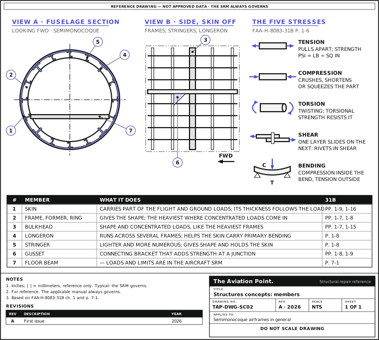
| Skin (stressed skin) | Carries part of the flight and ground loads with the spars, ribs, frames and stringers; its thickness changes with the load at each place | FAA-H-8083-31B pp. 1-9, 1-16 |
| Former, frame, ring | Give the fuselage its shape; the heaviest sit where concentrated loads and fittings come in. Makers' names differ | pp. 1-7, 1-8 |
| Bulkhead | Shape and concentrated loads, like the heaviest frames. At the wing root, the butt rib is also called the compression or bulkhead rib | pp. 1-7, 1-15 |
| Longeron | Runs across several frames and helps the skin carry the primary bending loads; one piece or built up | p. 1-8 |
| Stringer | Lighter and more numerous; gives shape and holds the skin. With the longerons it keeps tension and compression from bending the fuselage | p. 1-8 |
| Web members, gussets | Vertical or diagonal bracing between longerons and stringers; a gusset is a connecting bracket that adds strength | pp. 1-8, 1-9 |
| Spar | Main spanwise member of the wing: I-beam, with or without stiffeners, or sine-wave web; some are built fail-safe | pp. 1-12, 1-13 |
| Rib | Chordwise member giving the airfoil shape; nose and false ribs ahead of and behind the spars | pp. 1-14, 1-15 |
| Beams, struts, bars, tie rods | In a truss every member carries tension or compression; in a wing truss, drag and anti-drag wires (tie rods) resist chordwise loads | pp. 1-7, 1-15 |
| Wing struts, jury struts | A semicantilever wing passes part of its load through external struts or wires; short jury struts steady long struts | p. 1-10 |
| Wing attach fittings | At the inboard end of the spars: the strong, secure attachment to the fuselage, under removable root fairings | p. 1-15 |
| Empennage | Stabilizers are built much like wings; the tail cone is lighter because it receives less stress | p. 1-21 |
| Floor beams and floor panels | —: their loads and limits are in the aircraft SRM. The handbook lists them among composite applications | p. 7-1 |
| Doubler | Reinforcing plate riveted under the skin, as behind a flush patch or a cut-out | FAA-H-8083-31B ch. 4 |
Page numbers are FAA-H-8083-31B. The manufacturer's names govern: one maker's ring is another's frame (p. 1-8).
How it is built
| Construction | Who carries the load | Source |
|---|---|---|
| Truss | Welded steel tube, or riveted aluminum, members carry tension and compression; usually fabric covered | FAA-H-8083-31B p. 1-7 |
| Monocoque | The skin carries the primary stresses; formers, frames and bulkheads only give shape. Strength for the weight is its problem | p. 1-7 |
| Semimonocoque | Skin with longerons, stringers, frames and bulkheads. No single piece is failure critical, so it can take considerable damage. Most modern aircraft, nearly all pressurized ones | pp. 1-7 to 1-9 |
| Reinforced shell | The skin is reinforced by a complete framework | p. 1-9 |
| Full cantilever / semicantilever wing | No external bracing / external struts or wires | p. 1-10 |
| Monospar, multispar, box beam | One main spar, several, or two main spars joined by bulkheads; transport aircraft often use the box beam | pp. 1-11, 1-12 |
| Stressed-skin and wet wing | The skin shares the load; with sealed joints the structure itself is the fuel tank | p. 1-16 |
| Honeycomb panels | Used as skin on stressed-skin wings | p. 1-17 |
The five stresses
| Stress | What it is | Source |
|---|---|---|
| Tension | Resists a force that pulls apart. Tensile strength (psi) = breaking load (lb) ÷ cross-section (sq in) | FAA-H-8083-31B p. 1-6 |
| Compression | Resists a crushing force; shortens or squeezes the part | p. 1-6 |
| Torsion | Twisting; torsional strength is the resistance to it | p. 1-6 |
| Shear | One layer sliding over the next. Riveted plates in tension put the rivets in shear; shear strength is usually equal to or less than tensile or compressive strength | p. 1-6 |
| Bending | A combination: compression on the inside of the bend, tension on the outside | p. 1-6 |
| Stress and strain | Stress is the internal resistance to a load; strain is the deformation it causes | pp. 1-5, 1-6 |
| Pressurization | Cycling from unpressurized to pressurized on every flight causes metal fatigue | p. 1-9 |
Members are mostly designed for end loads (tension or compression) rather than side loads (bending). The handbook asks the technician to understand them so as not to change the original design by an improper repair (p. 1-5).
Members and stresses
Structural classification
| Class | Meaning | Source |
|---|---|---|
| Primary structure; principal structural element (PSE) | Contributes significantly to carrying flight, ground or pressurization loads. The certification evaluation identifies the elements whose failure could be catastrophic. Example: highly loaded skins and the understructure | AMC 25.571 par. 4; 14 CFR 25.571(a); TO 1-1A-1 par. 3.11.2 |
| Secondary structure | Carries less load. The example given is fairings, whose cracks go to the maintenance officer for appraisal; cowlings and fairings need shape more than strength | TO 1-1A-1 par. 3.11.2; FAA-H-8083-31B p. 1-7 |
| Tertiary structure | —: named in the Part-66 syllabus, not defined in the documents used here. The aircraft SRM gives the class of each part | EASA Part-66 App. I, module 11.2 |
| Single load path | The load goes through one member | AMC 25.571 par. 4 |
| Multiple load path | The load is spread through redundant members | AMC 25.571 par. 4 |
The SRM, not the look of the part, decides its class, and the allowable damage follows the class and the zone.
Safe-life, fail-safe, damage tolerance
| Concept | Meaning | Source |
|---|---|---|
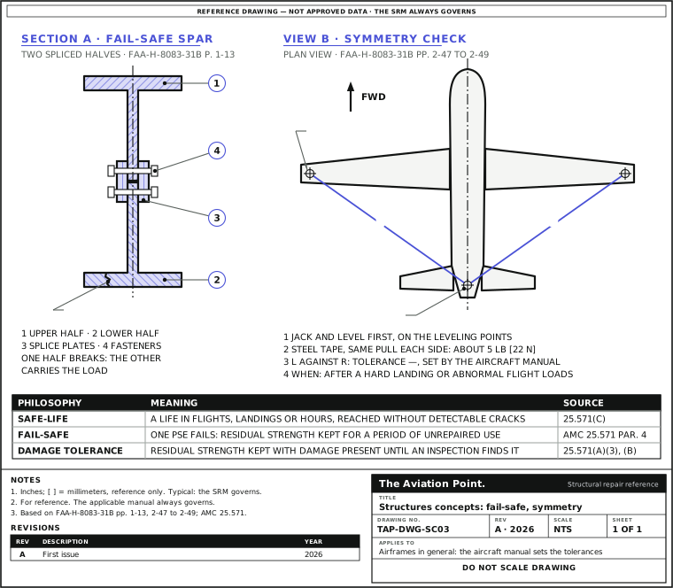
| Safe-life | A number of flights, landings or hours during which there is a low probability that fatigue cracking takes the strength below design. The part must reach it without detectable cracks, with scatter factors. Used where damage tolerance is impractical | AMC 25.571 par. 4; 14 CFR 25.571(c) |
| Fail-safe | After the failure or partial failure of one PSE the structure keeps its required residual strength for a period of unrepaired use. Example: a spar made of two spliced halves; if one breaks, the other carries the load | AMC 25.571 par. 4; FAA-H-8083-31B p. 1-13 |
| Damage tolerance | The structure keeps its required residual strength with fatigue, corrosion or accidental damage present, until an inspection finds it. Those inspections go into the Airworthiness Limitations section | AMC 25.571 par. 4; 14 CFR 25.571(a)(3), (b) |
| Widespread fatigue damage (WFD) | Cracks at many details at once, big and dense enough that the structure no longer meets its residual strength. MSD: in the same element; MED: in adjacent elements | AMC 25.571 par. 4 |
| Limit of validity (LOV) | Flight cycles or hours, or both, up to which it is shown that WFD will not occur; the maintenance program is valid up to it | 14 CFR 25.571(b); AMC 25.571 par. 4; AC 120-104 |
These are the transport-category rules (14 CFR Part 25, CS-25). The certification basis of each type decides which apply.
2Allowable damage
Why the class and the philosophy set the limit
The same scratch can be negligible in one place and a repair in another, because the members do not carry the same load. TO 1-1A-1 par. 3.11.2 sends a crack in a fairing to the maintenance officer for appraisal, and requires a crack in highly loaded skin or understructure to be repaired to the system's repair manual, with its allowable damage charts by structure.
In damage-tolerant structure the inspection is part of the design. A repair changes the structure the inspection was planned for, so it may need its own damage-tolerance inspection (AC 120-93; see damage classification) and, on a pressurized fuselage, a repair assessment (AC 120-73).
A semimonocoque structure tolerates damage because no single piece is failure critical (FAA-H-8083-31B p. 1-9). That is a property of the intact structure, not an allowance for the damage you found.
Aging aircraft and corrosion programs
| Program | What it does | Source |
|---|---|---|
| Continuing structural integrity program | The frame for the others: supplemental inspections, repairs and alterations, mandatory modifications, corrosion prevention and control, repair assessment | AC 91-56B par. 5g(1); AMC 20-20B sect. 5 |
| SSID / SSIP | The damage-tolerance-based inspection program: supplemental structural inspection document and Airworthiness Limitations inspections | AMC 20-20B sect. 6 and app. 1; AC 91-56B par. 1 |
| SB review, mandatory modification | Structural service bulletins reviewed; the modifications needed for continued airworthiness made mandatory | AC 91-56B par. 8; AMC 20-20B app. 3, annex 4 |
| CPCP | A systematic approach to prevent and control corrosion; the aim is to keep it at Level 1 or better | AMC 20-20B sect. 9 and app. 4; AC 91-56B par. 9 |
| Repairs and modifications | Damage-tolerance evaluation of repairs and changes; repair assessment of pressurized fuselages | AMC 20-20B sect. 7; AC 120-93; AC 120-73 (14 Dec 2000) |
| LOV and WFD | WFD evaluation, and the limit of validity of the maintenance program | AMC 20-20B sect. 8; AC 120-104 |
On the hangar floor these arrive as tasks with their own method and interval: SSIDs, SBs and ADs name the NDI method (AC 43.13-1B pars. 5-1, 5-6). The corrosion levels are defined in the type's CPCP.
Alignment and symmetry checks
| Item | What the handbook says | Source |
|---|---|---|
| When | Dihedral and incidence after hard landings or abnormal flight loads, to show nothing is distorted | FAA-H-8083-31B p. 2-48 |
| Before | Jack and level the aircraft; weight and loading as the manual says, never above the maximum jacking weight; in a closed hangar, or nose into wind | pp. 2-47, 2-48 |
| Leveling | Spirit level and straight edge on the leveling pegs or blocks; on large aircraft, a grid plate and plumb bob | p. 2-47 |
| The checks | Wing dihedral and incidence, fin verticality, engine alignment, symmetry, stabilizer incidence and dihedral | p. 2-48 |
| Dihedral | The maker's boards, or a straight edge and inclinometer, at the specified positions, normally on the front spar | p. 2-48 |
| Incidence | At least two positions on the wing, to show it is free from twist | p. 2-48 |
| Fin verticality | From set points on each side of the fin top to set points on each stabilizer; similar within limits | pp. 2-48, 2-49 |
| Symmetry | Steel tape between the checkpoints, with a spring scale for equal tension: about 5 lb [22 N] pull. Large aircraft: plumb bobs and chalk marks on the floor | p. 2-49 |
| Tolerances | — | The aircraft's maintenance or service manual (p. 2-49) |
The checks after a heavy landing or flight through turbulence are on Inspections after abnormal events.
Fail-safe spar and symmetry check
3Repair
Before a structural repair
| Step | Action | What to do |
|---|---|---|
| 1 | Locate it | Station, buttock line, water line and zone, in the maker's system (locating damage). |
| 2 | Name the member and its class | From the SRM, with the allowable damage chart for that structure (TO 1-1A-1 par. 3.11.2). |
| 3 | Trace the load path | What the member carries and which neighbors take its load now; inspect them as well. |
| 4 | Keep the original design | Restore the strength without changing the design (FAA-H-8083-31B p. 1-5): repair principles, splices, patches. |
| 5 | Restore the protection | Conversion coat, primer and sealant (finish, sealing, corrosion). |
| 6 | Plan the inspections | Damage-tolerance inspection of the repair where the program asks for it (AC 120-93); repair assessment on a pressurized fuselage (AC 120-73); the NDI method from the procedure (NDI methods). |
| 7 | Record | Location, member, data used and the inspections that follow (14 CFR 43.9). |
Worked example: reading a symmetry check
After a hard landing the manual calls for a symmetry check. The numbers are drawn for the format; the real checkpoints and tolerances are the aircraft's.
- The manual gives a checkpoint on each wing tip and one on the fuselage center line aft. Measure each wing point to the aft point with a steel tape and a spring scale at about 5 lb [22 N], the same pull on both sides (FAA-H-8083-31B p. 2-49).
- Left: 312 1/4 in. Right: 312 1/2 in. Difference: 1/4 in = 0.250 in [6.4 mm].
- Compare with the manual's tolerance for that pair: —, the manual sets it. Within it, record the figures and go on to cable tension and surface travel (p. 2-49). Outside it, the aircraft is not symmetrical: the manual's procedure and engineering decide what follows.
A 1/4 in [6.4 mm] difference is a number, not a verdict: the tolerance for that pair of checkpoints in the aircraft manual decides.
Quick check
A spar is made of two halves spliced together, so that if one cracks the other still carries the load. Which concept is that?
- Safe-life
Not this one. No: a safe-life part must reach its life without detectable cracks (14 CFR 25.571(c)); it does not count on another member.
- Fail-safe
Best fit. Yes: another part of the structure takes the load of the failed member (FAA-H-8083-31B p. 1-13; AMC 25.571 par. 4).
- Monocoque
Not this one. No: monocoque relies on the skin, with no other bracing (FAA-H-8083-31B p. 1-7).
On a real job, the SRM decides.
Questions people actually ask
Is a fairing primary or secondary structure?
Fairings are the secondary-structure example of TO 1-1A-1 par. 3.11.2. The SRM of the type gives the class of each part, and that is the one that counts.
Fail-safe or damage tolerance: what is the difference?
Fail-safe: residual strength after one PSE has failed, for a period of unrepaired use. Damage tolerance: residual strength with damage present until an inspection finds it, so the inspections are part of the design (AMC 25.571 par. 4; 14 CFR 25.571(a)(3)).
Who sets the inspection thresholds and intervals?
They come from the damage-tolerance evaluation of the type and go into the Airworthiness Limitations section (14 CFR 25.571(a)(3)). The task that reaches the hangar, from an SSID, SB or AD, names the NDI method (AC 43.13-1B pars. 5-1, 5-6).
What is the LOV?
The limit of validity of the maintenance program: the flight cycles or hours up to which it is shown that widespread fatigue damage will not occur (14 CFR 25.571(b); AC 120-104).
Why are nearly all pressurized aircraft semimonocoque?
Pressure cycling on every flight causes fatigue, and the semimonocoque spreads the load so that no single piece is failure critical (FAA-H-8083-31B p. 1-9).
Limits of this guide
What the sources support, and no further.
- The SRM governs. Class, allowable damage and repair of each part are the type's.
- No tolerances for alignment or symmetry are given: the maintenance manual has them.
- Damage-tolerance terms are those of the transport-category rules; other types may have another basis.
- Tertiary structure is not defined in the documents used here.
- Corrosion levels are defined in each type's CPCP; they are not restated here.
- mm and N values are converted from the inch and pound values of the documents.
Where to buy
Are you a distributor? Get listed →
Distributors coming soon.
Keep going
Calculators
Guides
How to do it
Books
Main sources
- FAA-H-8083-31B, Aviation Maintenance Technician Handbook — Airframe (2023) — Ch. 1, pp. 1-5 to 1-17 and 1-21 (stresses, fuselage and wing construction, fail-safe spar, empennage); ch. 2, pp. 2-47 to 2-49 (structural alignment, symmetry check); ch. 4 (doubler); p. 7-1 (floor beams).
- 14 CFR 25.571, Damage-tolerance and fatigue evaluation of structure — Pars. (a), (a)(3), (b) and (c).
- EASA CS-25, AMC 25.571 — Par. 4: definitions of damage tolerance, fail-safe, safe-life, PSE, single and multiple load path, WFD, MSD, MED, LOV.
- FAA AC 91-56B, Continuing Structural Integrity Program for Airplanes (7 March 2008) — Par. 5g(1), the elements besides the SSIP; par. 8, mandatory modification; par. 9, CPCP; par. 10, repair assessment; par. 4, AC 120-73 and AC 120-93 with their dates.
- EASA AMC 20-20B, Continuing structural integrity program — AMC-20 Amendment 22 (ED Decision 2021/007/R): sections 5 to 9; appendix 1, SSIP; appendix 3 and its annex 4, service bulletin review; appendix 4, CPCP.
- FAA AC 120-73, Damage Tolerance Assessment of Repairs to Pressurized Fuselages (14 December 2000) — Repair assessment.
- FAA AC 120-93, Damage Tolerance Inspections for Repairs and Alterations (2007) — Damage-tolerance inspections of repairs.
- FAA AC 120-104, Establishing and Implementing Limit of Validity to Prevent Widespread Fatigue Damage — LOV and WFD.
- TO 1-1A-1 / NAVAIR 01-1A-1, General Manual for Structural Repair — Par. 3.11.2: cracks in primary and secondary structure.
- AC 43.13-1B with Change 1 — Pars. 5-1 and 5-6: the documents that name the NDI method.
- 14 CFR Part 43, par. 43.9 — Maintenance record content.
- EASA Part-66 Appendix I (Regulation (EU) 2023/989) and FAA-S-ACS-1 — Modules 11.2 and 7.18(b); AM.II.D.
Cross-checked with other manuals and standards in our library.