1Identification
Where to buyWhat triggers each inspection
| Event | Trigger in public documents | Threshold | Source |
|---|---|---|---|
| Hard landing | A rough landing, even below the design landing weight: the vertical speed at contact is hard to judge | — : the AMM 05-51 of the type | FAA-H-8083-30B ch. 10 |
| Overweight landing | A landing at a weight known to exceed the design landing weight | — : the type's landing weight limit | FAA-H-8083-30B ch. 10 |
| Severe turbulence, over-g, violent maneuvers | Flight through severe turbulence; reported violent maneuvers | — : the AMM; load-factor limits are the type's | FAA-H-8083-30B ch. 10; TO 1-1A-1 2.1.2 |
| Lightning strike | Any strike that has occurred | Any strike | FAA-H-8083-30B ch. 10 |
| HIRF exposure | — : no public document sets a structural inspection; HIRF protection is kept by the maintenance in the ICA | — : the AMM of the type | AMC 20-158A 10 |
TO 1-1A-1 2.1.2: any aircraft that has reported violent flight maneuvers or hard landings must be thoroughly inspected in accordance with the applicable manuals.
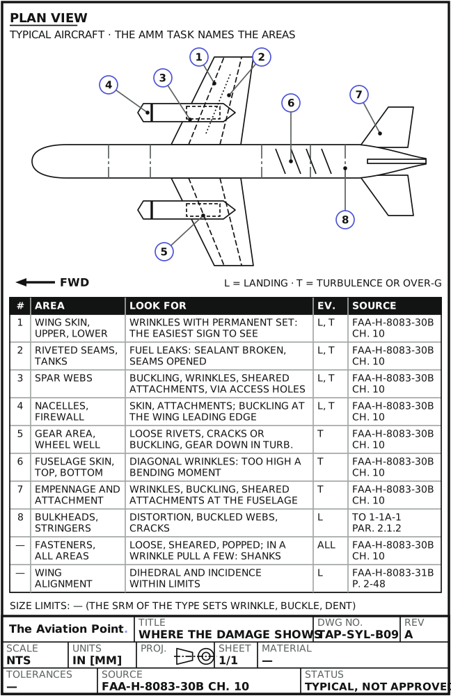
Where the damage shows
| Area | What to look for | Event | Source |
|---|---|---|---|
| Wing skin | Wrinkles: the most easily detected sign of an excessive landing load. Upper and lower surfaces: buckles or wrinkles with permanent set | Landing; turbulence | FAA-H-8083-30B ch. 10; TO 1-1A-1 1.5.3.4 |
| Riveted seams and tanks | Fuel leaks along riveted seams: overloads broke the sealant and opened the seams | Landing; turbulence | FAA-H-8083-30B ch. 10 |
| Spar webs | Buckling, wrinkles and sheared attachments, fuselage to tip, through the access openings | Landing; turbulence | FAA-H-8083-30B ch. 10 |
| Fasteners | Loose, sheared or popped. In a wrinkled area remove a few rivets and look at the shanks for shear | All | FAA-H-8083-30B ch. 10; TO 1-1A-1 2.1.2 |
| Bulkheads and stringers | Distortion, buckled webs, cracks | Landing | FAA-H-8083-30B ch. 10; TO 1-1A-1 2.1.2 |
| Nacelles and firewall | Nacelle skin and attachments, buckling at the wing leading edge, firewall skin | Landing; turbulence | FAA-H-8083-30B ch. 10 |
| Landing gear area | Loose rivets, cracks or buckling round the gear if it was down in turbulence; the wheel well | Turbulence | FAA-H-8083-30B ch. 10 |
| Fuselage skin, top and bottom | Diagonal wrinkles left by an excessive bending moment | Turbulence | FAA-H-8083-30B ch. 10 |
| Empennage | Wrinkles, buckling or sheared attachments on the surfaces and at the attachment to the fuselage | Turbulence | FAA-H-8083-30B ch. 10 |
| Rivet rows and fittings | Small cracks leading away from rivets; overstress cracks | All | TO 1-1A-1 1.5.3.4.1; AC 43.13-1B 5-5e(2) |
| Composite structure | Delamination, disbonding, broken fibers, core crushing | All | TO 1-1A-1 1.5.3.4 |
| Wing dihedral and incidence | Angles within limits, components not distorted | Landing; abnormal flight loads | FAA-H-8083-31B p. 2-48 |
These lists are general guidance; the AMM task of the type names the areas, their order and the method.
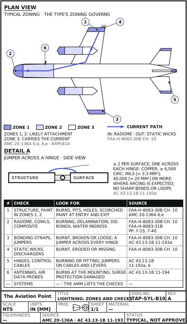
Lightning: where it goes in and out
| Item | What public documents say | Source |
|---|---|---|
| Zones | Zones 1 and 2 are where lightning is likely to attach; zone 3 carries the current between attachment points. Zoning is defined by SAE ARP5414 / EUROCAE ED-91A; the type's manual shows its own zones | AMC 20-136A 6.d, 6.e, appendix 1 |
| Exit | The current is meant to discharge at controlled points: static discharge wicks or null field dischargers | FAA-H-8083-30B ch. 10 |
| Metal and non-metal | Through good conductors (aluminum, steel) damage is usually minimal; through non-metallic parts without built-in bonding (radome, cowl, fairing, windows, composite) burning and worse damage can occur | FAA-H-8083-30B ch. 10 |
| Hinges and controls | A struck control surface can burn its hinges; jumpers across each hinge, and on cables and levers near the surface, keep the current out of the control system | AC 43.13-1B 11-193 |
| Antennas and probes | Need a path for lightning current to the airframe and protection against surges entering through cables | AC 43.13-1B 11-194 |
| Radome | Thin non-conducting sandwich in front of the aircraft: exposed to hail, birds and lightning; low-impact damage can cause disbonds and delamination, and water gets in | FAA-H-8083-31B p. 7-40 |
2Allowable damage
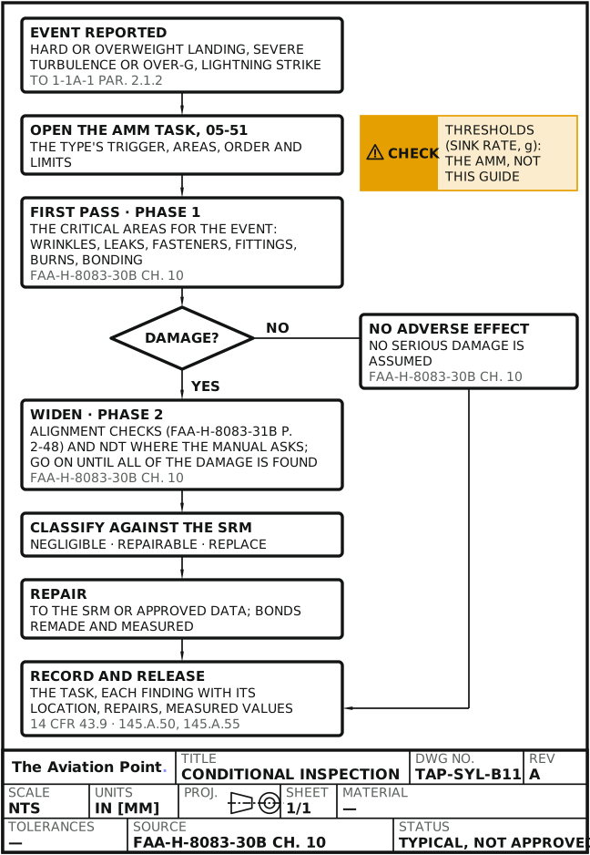
How the inspection is staged
The public guidance is the same for every event. Inspect the critical areas first. If none shows adverse effects, it is reasonable to assume no serious damage occurred. If damage is found, inspect further, with an alignment check, and keep going until all of the damage is found (FAA-H-8083-30B, chapter 10, special inspections).
The AMM task (chapter 05, usually 05-51) turns this into its own stages for the type, often called phase 1 and phase 2: a first set of areas for every event of that kind, and a wider set only when the first finds damage or the recorded severity calls for it. The stages, the areas and the limits are the manual's, not this guide's.
Damage found is classified against the SRM: negligible, repairable or replace. See damage classification and, to record where it is, locating damage.
What the public documents set
| Item | Published | Source |
|---|---|---|
| Hard-landing threshold (sink rate, g) | — : the AMM 05-51 of the type | — |
| Turbulence or over-g threshold | — : the AMM; the type's load-factor limits | — |
| Wrinkle, buckle or dent size | A wrinkle or buckle with permanent set is damage to assess; size limits: — : the SRM of the type | FAA-H-8083-30B ch. 10 |
| Rivets in a wrinkled area | Remove a few and check the shanks for shear; acceptance: the SRM | FAA-H-8083-30B ch. 10 |
| Control-surface lightning jumpers | At least one 6,500 circular mil copper jumper (about 3.3 mm²) across each hinge, not less than two per surface; 40,000 circular mils (about 20 mm²) or more where arcing is expected; no sharp bends or loops | AC 43.13-1B 11-193a |
| Bond resistance after a strike | — : the AMM value; public classes, limits and method in electrical bonding | AC 43.13-1B 11-187b |
| Heat-damaged metal | Hardness or conductivity tests on the affected metal, per TO 33B-1-1 | TO 1-1A-1 2.1.4 |
Circular mils converted by us: 1 circular mil ≈ 0.000507 mm². Where the AMM or the SRM gives a value, it governs.
After a lightning strike: what to check
| Check | Look for | Source |
|---|---|---|
| Structure and paint in zones 1 and 2 | Burns, pits, holes, scorched paint at the entry and exit points | FAA-H-8083-30B ch. 10; AMC 20-136A 6.e |
| Radome, cowls, fairings, windows, composite | Burning, discoloration, delamination, disbonds, water ingress. Composite strike protection: lightning protection; radome: radome repair | FAA-H-8083-30B ch. 10; FAA-H-8083-31B pp. 7-15, 7-40 |
| Bonding straps and jumpers | Burnt, broken or loose; the jumpers across every control-surface hinge in place | FAA-H-8083-30B ch. 10; AC 43.13-1B 11-193a |
| Static wicks and null field dischargers | Burnt, eroded or missing | FAA-H-8083-30B ch. 10 |
| Hinges and control cables | Burning or pitting at the hinges; jumpers on cables and levers near the surface | AC 43.13-1B 11-193a, b |
| Antennas and air data probes | Burns at the mounting, damaged surge protection | AC 43.13-1B 11-194 |
| Systems | — : the AMM lists the system and functional checks for the type | — |
Lightning and HIRF protection: what keeps it working
| Item | Lightning (AMC 20-136A) | HIRF (AMC 20-158A) |
|---|---|---|
| Maintenance in the ICA | Minimum maintenance to support lightning certification identified in the ICA (10.a) | Minimum maintenance to support HIRF certification identified in the ICA; dedicated devices or features need defined procedures (10.a) |
| What degrades it | Corrosion, fretting and flexing cycles on protection devices; replacement times where applicable (10.b) | Corrosion, fretting, flexing cycles or other causes; replacement times where applicable (10.b) |
| Fleet watch | A protection assurance program may sample the fleet (10.a) | A HIRF protection assurance program may sample the fleet (10.a) |
| Modifications | Assessed for their effect on the protection, by analysis or measurement (10.c) | Assessed for their effect on HIRF protection, by analysis or measurement (10.c) |
These AMCs are certification texts. In service, the AMM and the ICA of the type say which protection features to inspect after an event.
Bonding checks
Every conducting object on the outside of the airframe must be connected to it through joints, conductive hinges or bond straps able to carry static charges and lightning current (AC 43.13-1B 11-187b). After a strike, inspect the straps and jumpers on the current path and measure what the AMM asks for. Public bond classes, resistance limits and the measuring method are in electrical bonding.
3Repair
Step by step: a conditional inspection
| Step | Action | What to do |
|---|---|---|
| 1 | Take the report | The event, the date, the weight and what the crew or the walk-around found. A reported hard landing or violent maneuver is inspected (TO 1-1A-1 2.1.2). |
| 2 | Open the AMM task | Chapter 05, usually 05-51, for that event: trigger, areas, order and limits of the type. |
| 3 | First pass | The areas listed for the event: wrinkles with permanent set, fuel leaks at seams, popped or sheared fasteners, cracks at fittings and attachments, burns and bonding after a strike. |
| 4 | Widen when you find damage | Continue until all of the damage is found, with alignment checks where the manual asks (FAA-H-8083-30B ch. 10; dihedral and incidence, FAA-H-8083-31B p. 2-48). How the symmetry checks are made: Structures concepts. |
| 5 | NDT where the manual calls for it | Penetrant for surface cracks on nonporous parts (AC 43.13-1B 5-60); magnetic particle on landing gear components, splice and attach fittings (5-42); hardness or conductivity on heat-damaged metal (TO 1-1A-1 2.1.4). |
| 6 | Classify and repair | Each finding against the SRM: negligible, repairable or replace. Repairs to the SRM or approved data; bonds remade and measured. |
| 7 | Record and release | The AMM task done, findings with their location, repairs, measured values, then the release to service. |
Records
| Item | What it holds | Source |
|---|---|---|
| Maintenance record entry (FAA) | Description of the work or reference to acceptable data, date of completion, name of the person who did it, and the signature, certificate number and kind of certificate of the person approving return to service | 14 CFR 43.9(a) |
| Major repair (FAA) | FAA Form 337; AC 43.13-1B data cited in block 8 only where it applies | AC 43.13-1B par. 1 |
| Release and records (EASA) | Certificate of release to service and maintenance records of the organization | Part-145, 145.A.50 and 145.A.55 |
| Location of each finding | Station, waterline, buttock line, zone; see locating damage | — |
| The event itself | — : the operator's and the authority's occurrence reporting rules | — |
Worked example: a strike found on the walk-around
A small burn mark on the radome nose and a burnt static discharger on the left aileron trailing edge are found on the walk-around. A drawn case for the format; the AMM task of the type governs every step.
- Trigger: a strike has occurred, so the lightning inspection is due (FAA-H-8083-30B ch. 10). Open the AMM 05-51 task.
- Entry on the radome, a zone 1 area; exit at the discharger, a controlled exit point (AMC 20-136A 6.e; FAA-H-8083-30B).
- Radome: non-metallic, so look for burning, delamination, disbonds and water (FAA-H-8083-31B p. 7-40). Repair by the SRM; see radome repair.
- Aileron: the jumpers across each hinge and on the cables near the surface (AC 43.13-1B 11-193); hinges and bearings for burning or pitting; replace the discharger.
- Measure the bonds the AMM names; method in the bonding guide.
- Record the task, each finding with its location, the repairs and the measured values; release.
Inspect the entry, the exit and the bonding on the path between them, by the AMM task; repair by the SRM; record the measured values.
Aircraft grounded after the event? Send an urgent AOG request: parts, a mechanic or an engineer from the AOG network.
Quick check
After severe turbulence you find wrinkles with permanent set on the upper wing skin. What does FAA-H-8083-30B say to do in that area?
- Remove a few rivets and check the shanks for shear
Best fit. Yes: FAA-H-8083-30B, chapter 10, severe turbulence inspection.
- Smooth the skin and release if there is no fuel leak
Not this one. A wrinkle with permanent set is damage; the inspection goes on.
- Nothing until the next scheduled check
Not this one. It is a conditional inspection: the event triggers it now.
On a real job, the SRM decides.
Questions people actually ask
What g or sink rate makes a landing hard?
No public document gives one. The AMM 05-51 of the type defines it. FAA-H-8083-30B notes that the vertical speed at contact is hard to judge, so a rough landing is inspected even below the design landing weight.
The crew is not sure it was hard. Inspect?
A reported hard landing or violent maneuver is inspected per the manuals (TO 1-1A-1 2.1.2). The AMM says what the recorded data allows.
Why pull rivets in a wrinkled area?
To see whether the shanks sheared or carried high shear (FAA-H-8083-30B ch. 10). A wrinkle can hide fasteners that no longer hold.
Does lightning damage an aluminum airframe?
Through good conductors damage is usually minimal. It concentrates at the entry and exit points, in non-metallic parts, at hinges, bonding jumpers and dischargers (FAA-H-8083-30B ch. 10; AC 43.13-1B 11-193).
What is checked after HIRF exposure?
Structure is not the issue. The ICA names the protection features to keep (AMC 20-158A 10) and the AMM the system checks.
Limits of this guide
What the sources support, and no further.
- The AMM and the SRM govern. Triggers, stages, areas and limits are the type's (AMM chapter 05, usually 05-51).
- No threshold is given here: sink rate, g and damage sizes are «—» and come from the manuals.
- Phase 1 and phase 2 are the manuals' names for their own stages; the public guidance only says inspect first, widen if damage is found.
- Lightning zones are the type's, drawn per SAE ARP5414 / EUROCAE ED-91A.
- AMC 20-136A and 20-158A are certification texts; they are quoted for what they say about maintaining the protection.
Where to buy
Are you a distributor? Get listed →
Distributors coming soon.
Keep going
Calculators
Guides
How to do it
Books
Main sources
- FAA-H-8083-30B, Aviation Maintenance Technician Handbook: General — Ch. 10, special inspections: hard or overweight landing, severe turbulence and over-g, lightning strike.
- FAA-H-8083-31B, Aviation Maintenance Technician Handbook: Airframe — P. 2-48, dihedral and incidence after hard landings; p. 7-15, discoloration from lightning; p. 7-40, radomes.
- FAA AC 43.13-1B CHG 1 — Par. 1, scope and Form 337; 5-5e(2), overstress cracks; 5-42, magnetic particle; 5-60, penetrant; 11-187b, exterior bonding; 11-193, lightning protection bonding; 11-194, antennas and air data probes.
- TO 1-1A-1 / NAVAIR 01-1A-1, General Manual for Structural Repair — Pars. 1.5.3.4 and 1.5.3.4.1, violent maneuvers, turbulence and hard landings; 2.1.2, abnormal stresses and inspection per the manuals; 2.1.4, heat damage tests.
- EASA AMC 20-136A, Aircraft Electrical and Electronic System Lightning Protection — 6.d and 6.e, zoning; 10, maintenance; appendix 1, zone definitions by SAE ARP5414B / EUROCAE ED-91A.
- EASA AMC 20-158A, Aircraft Electrical and Electronic System HIRF Protection — 10, maintenance, protection assurance and modifications.
- 14 CFR 43.9 and Part-145 (145.A.50, 145.A.55) — Maintenance records and release to service.
Cross-checked with other manuals and standards in our library.