1Identification
Where to buyProcesses used on aircraft
| Process | How it works | Where it is used | Source |
|---|---|---|---|
| Oxy-acetylene (gas) | Acetylene or hydrogen mixed with oxygen in the torch, flame around 6,300 °F (3,482 °C); filler rod into the puddle; aluminum under flux | Steel tube structure and thin sheet. Not the best method for stainless steel, magnesium or aluminum: oxidation, distortion, loss of ductility. On stainless or aluminum all flux must be removed: it may cause corrosion | AC 43.13-1B 4-75(b), 4-86a |
| TIG (GTAW) | Tungsten electrode, filler fed by hand, argon or helium shield. DC straight polarity for mild steel, stainless steel and titanium; AC for aluminum and magnesium | Fills most of the needs of aircraft maintenance | AC 43.13-1B 4-86d, figs. 4-29, 4-30 |
| MIG (GMAW) | Bare wire electrode fed through the torch, argon, helium or CO2 shield, low-voltage high-current DC | More for large-volume production than for repair | AC 43.13-1B 4-86c |
| Stick (SMAW) | Flux-coated rod; the slag must be chipped off to examine the weld | — : no aircraft repair use is stated | AC 43.13-1B 4-86b |
| Resistance spot and seam | Copper electrodes; current, pressure and dwell time matched to material and thickness; nugget size follows tip size | Thin sheet, mostly stainless; seam welding for fuel tanks. Repair of spot-welded 18-8 structure: manufacturer, DER or FAA instructions | AC 43.13-1B 4-87, 4-104 |
| Brazing (silver, copper, aluminum) | Nonferrous filler that melts above 800 °F (425 °C as printed) but below the base metal; the base metal does not melt; flux; capillary flow | Not for structural repairs. Silver brazing: high-pressure oxygen lines and parts under vibration and heat | AC 43.13-1B 4-88, 4-88a, 4-88(2)(a) |
| Soldering | Filler melts well below brazing temperature | Never to join structural members. Bonding jumpers: electrical bonding | AC 43.13-1B 4-74c, 4-88(4)(a) |
AC 43.13-1B par. 4-74: identify the metal, identify the process the part was built with, then choose the process and the filler for the repair.
Which metal may be welded, and how
| Metal or part | Status | Why, and the conditions | Source |
|---|---|---|---|
| 4130 chrome-moly tube and sheet | Allowed | Readily weldable (SAE 4100 series). Over 3/16 in (4.8 mm): preheat 300 to 400 °F (150 to 205 °C). TIG on wall under 0.120 in (3.0 mm): no preheat, post-weld stress relief recommended. 4130 | AC 43.13-1B 4-76; FAA-H-8083-31B pp. 5-16, 5-22 |
| Plain carbon (1000), nickel (2300), chrome-nickel (3100), low Ni-Cr-Mo (8600) steels | Allowed | Listed as readily weldable | AC 43.13-1B 4-76 |
| Members that depend on heat treatment | Only with approval | The more an alloy steel responds to heat treatment, the less weldable it is. Weld with a rod that gives heat-treated values, then heat treat to the manufacturer's specification; a heat-treated tubular spar needs the whole assembly reheat treated | AC 43.13-1B 4-85, 4-100 |
| Heat-treated alloy steel parts: bolts, turnbuckle ends, axle stubs | Not allowed | Heat treated to improve their properties; damaged axle stubs are replaced | AC 43.13-1B 4-89c, 4-102c |
| Parts strengthened by cold work: streamline wire, cables | Not allowed | Their strength comes from cold working | AC 43.13-1B 4-89a |
| Brazed or soldered parts | Not allowed | The braze or solder penetrates and weakens the hot steel. Never weld a joint that was brazed | AC 43.13-1B 4-81, 4-88, 4-89b |
| Austenitic stainless (300 series) | Check | All weldable except 303 and 303Se. Structural stainless is cold worked and loses strength when heated: by gas, only non-structural stainless welds satisfactorily (slightly carburizing flame, 1/16 in (1.6 mm) feather, tip one or two sizes smaller than for steel) | FAA-H-8083-31B pp. 5-16, 5-17, 5-22 |
| Aluminum 2024 and 7075 | Not allowed | The heat of welding causes severe cracking | AC 43.13-1B 4-89d |
| Aluminum 1100, 3003, 4043, 5052 | Allowed | Gas welding usually 0.031 to 0.125 in (0.8 to 3.2 mm) thick, tip one size larger than for steel. TIG on AC, argon preferred, no flux | FAA-H-8083-31B pp. 5-17, 5-23 |
| Aluminum 6053, 6061, 6151 | Only with approval | Used heat treated: weld only if the part can be reheat treated | FAA-H-8083-31B p. 5-17 |
| Magnesium | Check | High expansion: rigid fixtures, no joints that trap flux, butt and edge welds preferred. Never weld aluminum to magnesium. TIG current: the two documents differ. AC 43.13-1B fig. 4-30 sets AC; FAA-H-8083-31B p. 5-23 names DC either polarity or AC with high frequency, DC reverse polarity preferred by hand. The welding procedure of the repair data governs | FAA-H-8083-31B pp. 5-18, 5-19, 5-23; AC 43.13-1B fig. 4-30 |
| Titanium | Check | DC straight polarity; clean area free of drafts; puddle, trailing and back side shielded until the weld is below 800 °F (427 °C) | FAA-H-8083-31B pp. 5-23, 5-24 |
Statuses come from the documents cited: Allowed = the document names it weldable; Check = weldable with conditions; Only with approval = needs reheat treatment or engineering; Not allowed = the document says do not weld.
Filler rods to stock
| Rod | AMS | AWS | Welds |
|---|---|---|---|
| 4130 | AMS 6457 | AWS A5.18 | Mild steel, 4130 steel |
| 4140 | AMS 6452 | AWS A5.28 | 4140 steel |
| 4043 | AMS 4190 | AWS A5.10 | Most weldable aluminum |
| 308L | AMS 5692 | AWS A5.9 | 304 stainless steel |
| 316L | AMS 5692 | AWS A5.9 | 316 stainless steel |
| AZ61A | AMS 4350 | AWS A5.19 | AZ61A magnesium |
| ERTi-5 | AMS 4954 | AWS A5.16 | Titanium |
AC 43.13-1B par. 4-90 and table 4-15, as printed (308L and 316L both carry AMS 5692 there). The drawing or the repair data names the filler. Engine mounts: high-grade metallurgically controlled (mc) rods only (par. 4-99c).
Joint types and preparation
| Joint | Preparation | Source |
|---|---|---|
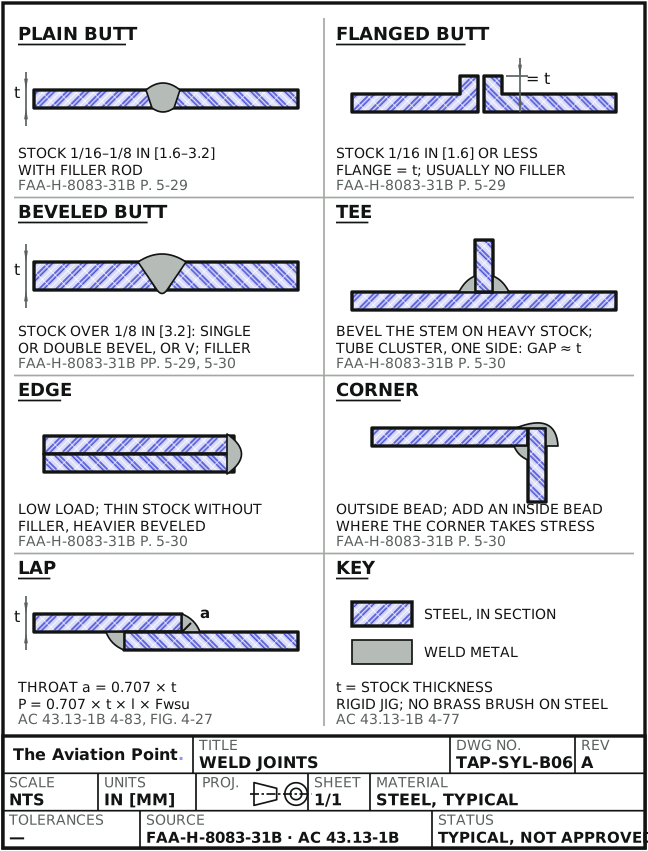
| Butt, plain | 1/16 to 1/8 in (1.6 to 3.2 mm) thick, with filler rod | FAA-H-8083-31B p. 5-29 |
| Butt, flanged | 1/16 in (1.6 mm) or less; flange equal to the thickness; usually no filler | FAA-H-8083-31B p. 5-29 |
| Butt, beveled | Over 1/8 in (3.2 mm): single or double bevel or V for full penetration, with filler. A crack repaired by welding is a butt joint: stop-drill both ends first, and it usually still needs reinforcement | FAA-H-8083-31B pp. 5-29, 5-30 |
| Tee | Plain for most aircraft thicknesses; bevel the vertical member on heavier stock. In tube clusters welded from one side, a gap about equal to the metal thickness helps full penetration | FAA-H-8083-31B p. 5-30 |
| Edge and corner | Where load is low; thin stock without filler, heavier stock beveled or with filler; an inside bead where a corner takes more stress | FAA-H-8083-31B p. 5-30 |
| Lap | Seldom in gas-welded structure, common in spot welding; the single lap resists bending poorly. Fillet throat = 0.707 × t; strength P = 0.707 × t × l × Fwsu | FAA-H-8083-31B pp. 5-30, 5-31; AC 43.13-1B 4-83, fig. 4-27 |
| Rosette | Hole in the outer tube only, about 1/4 of its diameter; edge distance 1/2 of the tube diameter; a 1/8 in (3.2 mm) hole in the inner tube under it bleeds the heat. Not counted for strength; may be omitted on tight sleeves | AC 43.13-1B 4-84 |
| Every joint | Rigid jig that holds alignment through expansion and contraction. Wire-brush clean, never with brass or bronze on steel; metallized surface sandblasted and buffed. TIG on 4130: stainless steel brush, all oil and paint off | AC 43.13-1B 4-77; FAA-H-8083-31B p. 5-22 |
2Allowable damage
Inspecting a finished weld
| Look at | Accept | Source |
|---|---|---|
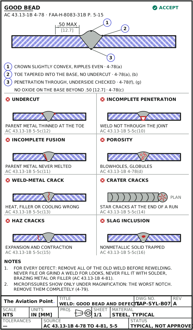
| Seam | Smooth, ripples evenly spaced, uniform thickness | AC 43.13-1B 4-78(a); FAA-H-8083-31B p. 5-15 |
| Contour | Built up slightly convex; tapered smoothly into the base metal; no undercut at the toe | AC 43.13-1B 4-78(a), (b); FAA-H-8083-31B p. 5-15 |
| Oxide | None on the base metal more than 1/2 in (12.7 mm) from the weld | AC 43.13-1B 4-78(c) |
| Porosity | No blowholes, porosity or projecting globules; numeric limits only where the specification on the drawing gives them (military specifications, ASTM codes) | AC 43.13-1B 4-78(d) |
| Base metal | No pitting, burning, cracking or distortion | AC 43.13-1B 4-78(e) |
| Penetration | Base metal and filler fused through the joint; underside checked | AC 43.13-1B 4-78(f), (g) |
| Scale and slag | Removed by wire brush or sandblasting; no roll-over, cold lap or unfused weld metal | AC 43.13-1B 4-78(g) |
| Titanium color | Bright silver. Straw: slight contamination, unlikely to affect properties. Dark blue or white powdery oxide: remove the whole weld and reweld | FAA-H-8083-31B p. 5-24 |
| Brazed joint | Filler drawn through the joint by capillarity, uniform bead. — : no other acceptance criteria in these documents; the drawing's or the process specification's | FAA-H-8083-31B p. 5-19 |
A smooth bead can still be weak inside; a rough, uneven, pitted one is almost always bad inside (FAA-H-8083-31B p. 5-15).
Weld defects
| Defect | What it is | Source |
|---|---|---|
| Microfissures | Cracks visible only under magnification; the worst defect: hard to find and the worst notch effect. Remove completely before welding | AC 43.13-1B 4-79 |
| Incomplete penetration | Weld metal did not go through the joint before solidifying | AC 43.13-1B 5-5c(10) |
| Incomplete fusion | Parent metal next to the weld never got hot enough to melt | AC 43.13-1B 5-5c(11) |
| Undercut | Parent metal thinned at the toe of the weld by welding too hot | AC 43.13-1B 5-5c(12) |
| Cracks in the weld metal | Thin section cooling faster than a heavy one, wrong heat or filler; among the most common weld flaws | AC 43.13-1B 5-5c(13) |
| Crater cracks | Star-shaped cracks at the end of a weld run | AC 43.13-1B 5-5c(14) |
| Heat-affected-zone cracks | From expansion and contraction stresses next to the weld | AC 43.13-1B 5-5c(15) |
| Slag inclusion | Nonmetallic solid trapped in the weld or between weld and base metal | AC 43.13-1B 5-5c(16) |
| Low-strength weld | Poor penetration or fusion, undercut, trapped oxides, slag or gas, overlap, too much or too little reinforcement, overheating | FAA-H-8083-31B p. 5-15 |
For every defect: remove all of the old weld before rewelding. Never file or grind a weld for looks and never fill it with solder, brazing metal or any filler; avoid welding over a weld, reheating can make the metal brittle (AC 43.13-1B 4-81).
Beyond the eye: NDT of welds
| Method | On welds | Source |
|---|---|---|
| Visual, with magnification | Every weld, both sides; microfissures may need magnification | AC 43.13-1B 4-78, 4-79 |
| Liquid penetrant | Nonporous metals; finds only discontinuities open to the surface. For stainless, aluminum, titanium welds | AC 43.13-1B 4-80, 5-60 |
| Magnetic particle | Ferromagnetic steel only (4130 tube, fittings); not on austenitic stainless, which is nonmagnetic | AC 43.13-1B 4-80, 5-42; FAA-H-8083-31B p. 5-22 |
| Radiography, ultrasonic, eddy current, acoustic emission | Listed for critical applications | AC 43.13-1B 4-80 |
NDT is advisable in critical applications and needs trained, qualified people (AC 43.13-1B 4-80). The drawing or the repair data says which method and to what standard.
Steel-tube damage: what each repair accepts
| Damage | Limit | Leads to | Source |
|---|---|---|---|
| Dent in a tube | Depth ≤ 1/10 D; ≤ 1/4 of the circumference; length ≤ D; no cracks, abrasions or sharp corners; reformable without cracking | Welded patch, same material, one gauge thicker | AC 43.13-1B 4-94a |
| Hole in a tube | Length ≤ D; ≤ 1/4 of the circumference | Welded patch | AC 43.13-1B 4-94b |
| Dent, bend or crack in a bay | — : no size limit; straighten, stop-drill crack ends No. 40 (0.098 in, 2.5 mm) | Welded split sleeve | AC 43.13-1B 4-91d, 4-92 |
| Dent at a cluster | — : no size limit published | Finger patch plate | AC 43.13-1B 4-91c |
| Section to replace | — | Inner-sleeve, outer-sleeve or larger-tube splice | AC 43.13-1B 4-95 to 4-97 |
| Filling a dent or crack with rod | Not allowed | Reinforce instead | AC 43.13-1B 4-92 |
| Bolted sleeve on welded tube | Only with approval of the manufacturer or the FAA | The bolt holes may be critical | AC 43.13-1B 4-93 |
| Engine mount, all members out of line | Not allowed to repair | Replace: manufacturer's mount or one built to its drawings | AC 43.13-1B 4-99d |
| Engine mount ring, extensive damage | Only with approval: FAA-approved method | Minor crack at a lug: reweld and extend a gusset or lug | AC 43.13-1B 4-99e |
D = outside diameter of the damaged tube. Look along the tube for secondary damage away from the visible dent, where the load path changes direction most abruptly (AC 43.13-1B 4-91a). The SRM of the type governs where it gives limits.
3Repair
Steel-tube repairs: the dimensions
| Repair | Key dimensions | Source |
|---|---|---|
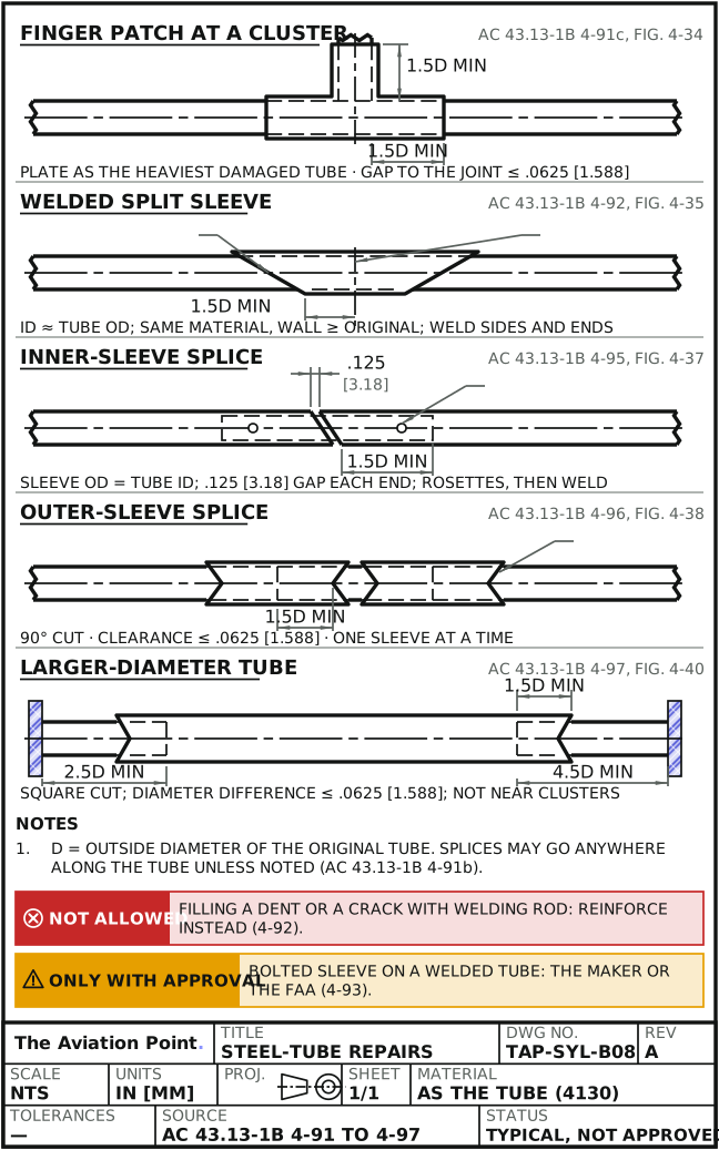
| Finger patch at a cluster | Plate of the material and thickness of the heaviest damaged tube; fingers ≥ 1.5 D over each tube; gap to the joint ≤ 1/16 in (1.6 mm); tack, then weld all edges | AC 43.13-1B 4-91c, fig. 4-34; FAA-H-8083-31B p. 5-31 |
| Welded split sleeve | ID about equal to the tube OD; same material, wall at least the original; 30° cut on both ends; near end ≥ 1-1/2 D from the dent or crack; weld both sides and both ends | AC 43.13-1B 4-92, fig. 4-35 |
| Welded patch | Same material, one gauge thicker; limits in the damage table | AC 43.13-1B 4-94, fig. 4-36 |
| Inner-sleeve splice | Diagonal cut; replacement tube same material and diameter, wall at least the original; 1/8 in (3.2 mm) gap at each end; sleeve OD = tube ID, diameter difference ≤ 1/16 in (1.6 mm); sleeve ends ≥ 1-1/2 D from the nearest end of the cut; rosette tacks, weld through the gap | AC 43.13-1B 4-95, fig. 4-37; FAA-H-8083-31B p. 5-32 |
| Outer-sleeve splice | 90° cut; replacement bears on the stubs within 1/32 in (0.8 mm) total; sleeve clearance ≤ 1/16 in (1.6 mm); sleeve ends ≥ 1-1/2 D from the cut; fishmouth where possible; weld one sleeve, let it cool, then the other. Most welding of all: only when the others do not suit | AC 43.13-1B 4-96, figs. 4-38, 4-39 |
| Larger-diameter replacement tube | Square cut; short stub ≥ 2-1/2 D, long stub ≥ 4-1/2 D; diameter difference ≤ 1/16 in (1.6 mm); ends ≥ 1-1/2 D from the cut; fishmouth where possible. Not close to cluster joints or where brackets need the original diameter | AC 43.13-1B 4-97, fig. 4-40 |
| Engine mount member | Larger-diameter tube telescoped over the stub with fishmouth and rosette welds; 30° scarf acceptable. Alignment kept with a fixture or by bolting to engine or airframe; cracked welds ground out; re-stress relieve if the maker did | AC 43.13-1B 4-99; FAA-H-8083-31B p. 5-35 |
D = outside diameter of the original tube. Splices may go anywhere along the tube unless noted (AC 43.13-1B 4-91b); brace-strut splices must not overlap an end fitting (4-101a).
Gas welding: torch tip for steel
| Steel thickness, in (mm) | Tip hole, in (mm) | Drill |
|---|---|---|
| 0.015 to 0.031 (0.38 to 0.79) | 0.026 (0.66) | No. 71 |
| 0.031 to 0.065 (0.79 to 1.65) | 0.031 (0.79) | No. 68 |
| 0.065 to 0.125 (1.65 to 3.18) | 0.037 (0.94) | No. 63 |
| 0.125 to 0.188 (3.18 to 4.78) | 0.042 (1.07) | No. 58 |
| 0.188 to 0.250 (4.78 to 6.35) | 0.055 (1.40) | No. 54 |
| 0.250 to 0.375 (6.35 to 9.53) | 0.067 (1.70) | No. 51 |
AC 43.13-1B par. 4-82, table 4-13 (inches); mm converted by us. Aluminum: one tip size larger than for steel of the same thickness (FAA-H-8083-31B p. 5-17); stainless: one or two sizes smaller (p. 5-17). The welding equipment maker's data governs the setting (AC 43.13-1B 4-75).
Step by step: a weld repair on 4130 tube
| Step | Action | What to do |
|---|---|---|
| 1 | Data and welder | Manufacturer's data or approved repair data; AC 43.13-1B only where it applies. A welder qualified for the group (AC 43.13-1B 4-74f). |
| 2 | Identify | The metal, its heat-treat condition and the original process. If identification is not positive: the manufacturer or a metallurgical laboratory (4-76). Heat-treated part: 4-85 or no weld. |
| 3 | Find all of the damage | Secondary damage along the tube (4-91a); cracks found and removed completely before welding (4-79). |
| 4 | Prepare | Finish off the repair area; clean, never with a brass or bronze brush on steel; rigid jig (4-77). Cut, deburr and fit to the dimensions of the repair. |
| 5 | Weld | Gas: neutral flame for most steels. TIG: DC straight polarity (4-86d). Over 3/16 in (4.8 mm) chrome-moly: preheat 300 to 400 °F (150 to 205 °C). Fillets flat or slightly convex, no draft, cool slowly (FAA-H-8083-31B pp. 5-16, 5-22). |
| 6 | Stress relieve | Where called for: the whole weldment to 1,100 to 1,200 °F (595 to 650 °C), about 45 minutes per inch of thickness; for most tube sections a minute or two (FAA-H-8083-31B p. 5-22). Heat-treated members: to the manufacturer's specification (4-85). |
| 7 | Inspect | AC 43.13-1B 4-78, both sides; NDT on critical parts (4-80). Engine mounts: alignment (4-99a). Struts: watch vibration over a range of speed and power on the first flights (4-101a). |
| 8 | Protect and record | Restore the finish. Record the work (14 CFR 43.9); major repair: FAA Form 337 (AC 43.13-1B par. 1). |
Brazing: the published rules
| Item | Rule | Source |
|---|---|---|
| Use | Not for structural repairs; not for parts that see sustained high temperature | AC 43.13-1B 4-88a; FAA-H-8083-31B p. 5-19 |
| Never | Weld over a brazed joint | AC 43.13-1B 4-81, 4-88 |
| Fit and flux | Parts held still, close fit for capillary flow; flux in all brazing (most are borax and boric acid) | AC 43.13-1B 4-88b; FAA-H-8083-31B p. 5-19 |
| Flame | Neutral for most; slightly oxidizing with copper-zinc, copper-zinc-silicon or copper-zinc-nickel-silicon fillers; aluminum neutral, slightly reducing if needed | AC 43.13-1B 4-88d |
| Heat | Base metal to the flow temperature of the filler; do not melt the rod with the torch; overheating to the filler's boiling point makes the joint porous and brittle | FAA-H-8083-31B p. 5-19 |
| Silver brazing lap | 4 to 6 times the metal thickness for strength equal to the base metal in the heated zone; inner cone about 1/2 in (12.7 mm) from the work, flame moving | AC 43.13-1B 4-88(2)(d), (e) |
| Copper brazing of steel | Controlled-atmosphere furnace; in any other conditions not recommended. Allowable shear 15 ksi (103 MPa) for all heat-treat conditions; base metal per table 4-14 | AC 43.13-1B 4-88(1) |
| After | Cool slowly; remove the flux (30 minutes in a lye solution) | AC 43.13-1B 4-88f |
Worked example: a dent between clusters in 4130 tube
A fuselage truss tube, 1 in (25.4 mm) OD, has a smooth dent 0.080 in (2.0 mm) deep and 0.75 in (19 mm) long over about 1/5 of the circumference, with no cracks. The sizes are drawn values for the format; the real ones are the aircraft's, and the SRM governs where it gives limits.
- Patch limits (AC 43.13-1B 4-94a): depth ≤ D/10 = 0.100 in (2.5 mm): 0.080 in passes. Circumference ≤ 1/4: passes. Length ≤ D = 1 in: 0.75 in passes.
- No cracks, abrasions or sharp corners, and it reforms without cracking: a welded patch of the same material, one gauge thicker, is acceptable.
- Had the dent been 0.120 in (3.0 mm) deep, the patch is out: a welded split sleeve (4-92). Its near ends ≥ 1-1/2 D from the dent, so the shortest sleeve = 0.75 + 2 × 1.5 = 3.75 in (95 mm) between the near points of the 30° ends.
- A truss member is primary structure: this is a major repair (14 CFR part 43, appendix A (b)(1)(xiv)). Approved data, qualified welder, Form 337.
Patch for the 0.080 in dent; a sleeve at least 3.75 in (95 mm) long if it were 0.120 in, both under approved data.
Quick check
By AC 43.13-1B par. 4-78, how far from a finished weld may oxide have formed on the base metal?
- No more than 1/2 in (12.7 mm)
Best fit. Yes: AC 43.13-1B 4-78(c).
- No more than 1 in, if it is wire-brushed
Not this one. The AC sets 1/2 in; brushing removes scale, it does not change the limit.
- Any distance: oxide is cosmetic
Not this one. Oxide past 1/2 in is a reject sign in 4-78(c).
On a real job, the SRM decides.
Questions people actually ask
Can 2024 or 7075 be welded?
No. AC 43.13-1B 4-89d: the heat of welding causes severe cracking. Repair them with fasteners per the SRM.
Can a cracked steel tube be brazed?
No. Brazing is not used for structural repairs (4-88a), and a brazed joint can never be welded afterwards (4-81).
Why not grind the bead smooth?
Filing or grinding a weld for looks costs strength (AC 43.13-1B 4-81; FAA-H-8083-31B p. 5-15). Scale and slag come off; the bead stays.
Gas or TIG on 4130?
Both are used. TIG fills most maintenance needs (4-86d). Over 0.093 in (2.4 mm), TIG with a proper post-weld heat treatment can give less distortion; do not skip that treatment, untempered martensite cuts fatigue life (FAA-H-8083-31B p. 5-16).
Who may weld on a certified aircraft?
A welder qualified for the metal group (AC 43.13-1B 4-74f), working to the manufacturer's or approved data. Many organizations run their own qualification tests or have a laboratory validate them (4-74h).
Limits of this guide
What the sources support, and no further.
- The manual governs. Manufacturer's data, approved repair data and the SRM come before AC 43.13-1B.
- AC 43.13-1B covers nonpressurized areas, only when there are no manufacturer instructions (par. 1).
- No porosity or defect sizes are given here: the specification the drawing calls up sets them (AC 43.13-1B 4-78d), for example AWS D17.1, Specification for Fusion Welding for Aerospace Applications. Older drawings may call up MIL-W-8611 (historical).
- Soldering appears only where it meets structure (never) and bonding (linked).
- Spot-welded stainless structure is repaired only to manufacturer, DER or FAA instructions (AC 43.13-1B 4-104).
- mm values are converted from the inch values of the documents; 800 °F is printed as 425 °C in AC 43.13-1B.
Where to buy
Are you a distributor? Get listed →
Distributors coming soon.
Keep going
Guides
Data sheets
Books
Buy
Distributors coming soon.
Main sources
- FAA AC 43.13-1B CHG 1, Acceptable Methods, Techniques, and Practices: Aircraft Inspection and Repair — Par. 1, purpose and Form 337 block 8; pars. 4-74 to 4-104, welding and brazing (tables 4-12 to 4-15, figs. 4-26 to 4-41); 4-112 and 4-115, safety; 5-5c(10) to (16), weld flaws; 5-42, magnetic particle; 5-60, penetrant.
- FAA-H-8083-31B, Aviation Maintenance Technician Handbook: Airframe — Ch. 5: pp. 5-15 to 5-19, good weld, 4130, chrome-moly, stainless, aluminum, magnesium, brazing; pp. 5-22 to 5-24, TIG on 4130, stainless, aluminum, magnesium, titanium; pp. 5-29 to 5-32, joints and tube repairs; p. 5-35, engine mounts and rosettes.
- 14 CFR part 43 — § 43.9, maintenance records; appendix A (b)(1), airframe major repairs.
- MIL-STD-1595A, Qualification of Aircraft, Missile and Aerospace Fusion Welders — Named by AC 43.13-1B 4-74g for welder groups.
- AWS D17.1, Specification for Fusion Welding for Aerospace Applications — Named as an example of a weld acceptance specification; not quoted.
- Regulation (EU) No 748/2012, Annex I (Part 21) — Subpart M, repairs.
Cross-checked with other manuals and standards in our library.