1Identification
Where to buyWhat each method finds and misses
| Method | Finds | Misses, or limits | Materials | Source |
|---|---|---|---|---|
| Visual, with light, mirror and magnifier | Surface cracks, corrosion, contamination, finish damage; buckled, bulging or dented skin; overheating marks; composite delamination signs | Surface only; generally only large flaws; scratches can be misread as cracks | All | AC 43.13-1B pars. 5-15, 5-18 h; table 5-1 |
| Borescope | Inside closed structure and engines: pitting, scoring, cracks, seal and part fit, foreign objects | Surface only, and only what the tip can see | All | AC 43.13-1B par. 5-17 |
| Tap test | Delamination or disbond near the surface; thin skin to stiffener bondlines; honeycomb with thin face sheets | Skins under 0.080 in [2.0 mm] only; the far bondline of a honeycomb panel needs access from the other side; no record; design details change the sound | Composite and bonded metal | AC 43.13-1B par. 5-105; FAA-H-8083-31B p. 7-15 |
| Liquid penetrant | Discontinuities open to the surface | Nothing below the surface; rough or porous surfaces; finish and sealant must come off; smeared metal can close the opening | Nonporous metals and non-metals, steel included | AC 43.13-1B pars. 5-60, 5-63 g; table 5-1 |
| Magnetic particle | Cracks, laps, seams, voids, pits at or slightly below the surface | Only iron and steel; a flaw parallel to the field; paint or chrome over 0.003 in [0.08 mm]; the part must be demagnetized after | Ferromagnetic only | AC 43.13-1B pars. 5-40, 5-41 a, 5-45 a; table 5-1 |
| Eddy current | Surface and subsurface cracks, pits, metal loss from corrosion on inner surfaces; usually through primer, paint and anodic film | Conductive material only; the probe must reach the surface; rough surfaces; slow over large areas; best on small local areas | Electrically conductive | AC 43.13-1B pars. 5-25, 5-27, 5-30; table 5-1 |
| Eddy current, conductivity | Alloy and heat-treat condition; heat damage after grinding, fire or overheating | Acceptance values: the NDT manual or the material specification sets them | Conductive metals | AC 43.13-1B pars. 5-25, 6-136; TO 1-1A-1 par. 2.1.4 |
| Ultrasonic | Cracks, porosity, delaminations, bond voids; thickness from one side | Needs couplant and an accessible surface; very sensitive to beam and flaw orientation; high skill to set up and read | Wide range of materials and thicknesses | AC 43.13-1B pars. 5-91, 5-92, 5-96; table 5-1 |
| Radiography (X-ray) | Internal flaws, hidden areas, water in honeycomb core, crushed core; gives a permanent record | Cracks only when nearly along the beam; tight cracks in thick sections; delaminations almost never; no depth; radiation hazard | Most; composites need low energy | AC 43.13-1B pars. 5-80, 5-81, 5-83; FAA-H-8083-31B p. 7-18 |
| Thermography | Debonds, cracks, impact damage, panel thinning, water in composites and honeycomb | Works best on thin laminates and near-surface flaws | Composite and bonded structure | AC 43.13-1B par. 5-120; FAA-H-8083-31B p. 7-18 |
AC 43.13-1B also lists acoustic emission, holography and shearography (pars. 5-112 to 5-134). The inspection document names the method; this table is for understanding it, not for choosing a different one.
What each method sees
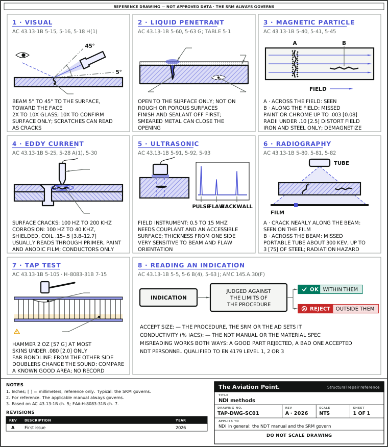
Who names the method, and what decides it
| Item | What the sources say | Source |
|---|---|---|
| Who names the method | The manufacturer's inspection, maintenance or overhaul manual, an AD, an SSID or an SB. Some ADs refer to SBs that refer to the manual | AC 43.13-1B pars. 5-1, 5-6 |
| Another method | Only with acceptable data, for example procedures developed by a 14 CFR part 145 repair station | AC 43.13-1B par. 5-1 |
| Factors | How critical the part is; material, size, shape and weight; flaw sought; acceptable flaw size; where and how flaws lie; access; number of parts | AC 43.13-1B par. 5-6 b |
| Sensitivity | A part that cannot tolerate a small flaw needs a more sensitive method | AC 43.13-1B par. 5-6 c |
| Confirmation | One inspection may show a possible flaw and another confirm it. Visual inspection often confirms flaws found by other methods | AC 43.13-1B pars. 5-6 a, 5-15 |
Table 5-1 is a guide for choosing only when neither the manufacturer nor the FAA has specified a method (AC 43.13-1B par. 5-6 e).
Who may do it: NDT qualification
| Level or rule | What it asks | Source |
|---|---|---|
| Level I Special | Classroom hours and on-the-job training for one specific task; vision and color-perception test; a general and a practical exam set by a Level II or III | AC 43.13-1B par. 5-3 a (ATA Spec 105) |
| Level I / Level II | An FAA airframe and powerplant certificate, the formal classroom hours and an exam: the certificate is the entry, not the qualification | AC 43.13-1B par. 5-3 b |
| Level III | Engineering or science degree and experience as a Level II in the method, or 4 years as a Level II and an exam | AC 43.13-1B par. 5-3 c |
| Reading eddy current, X-ray or ultrasonic indications | Qualified and certified to FAA or other accepted standards, such as MIL-STD-410 or ATA Spec 105 | AC 43.13-1B par. 5-4 |
| EASA Part-145 | NDT staff qualified to Level 1, 2 or 3 of EN 4179 for the NDT function they perform | AMC 145.A.30(f) par. 2 |
| Tap test | Read by ear, so only qualified personnel | AC 43.13-1B par. 5-105 b |
The qualification is per method. Who may sign the release after the inspection is a separate question, answered by the organization's approval.
2Allowable damage
Reading an indication
An indication becomes a defect only once it is judged. Each one is evaluated against the acceptable limits of the procedure (AC 43.13-1B par. 5-63 j). Misreading works both ways: a serviceable part rejected, or a defective one accepted (par. 5-5).
Some indications come from the design, not from a flaw. With magnetic particle, sharp radii under 0.10 in [2.5 mm] distort the field (par. 5-41 b). In a tap test, an internal doubler or stiffener changes the pitch on purpose (FAA-H-8083-31B p. 7-15). A known good area, or a standard, is the comparison (AC 43.13-1B par. 5-105).
Orientation decides what can be seen. The magnetic field must cross the expected flaw (par. 5-41 a). A crack shows on film only when it lies nearly along the beam (par. 5-81). Ultrasonic inspection is very sensitive to the angle between beam and flaw (table 5-1). A clean result is only as good as that geometry.
The numbers the public documents give
| Item | Value [mm] | Source |
|---|---|---|
| Flashlight angle for surface cracks | 5° to 45° to the surface, toward the face | AC 43.13-1B par. 5-18 h(1) |
| Magnifier to carry / to confirm a crack | 2 to 10 power / 10 power | AC 43.13-1B pars. 5-16, 5-18 h(1) |
| Magnification of a simple lens | M = 10 / f, f in inches: f = 5 in [127 mm] gives 2 power | AC 43.13-1B par. 5-16 c |
| Eddy current, surface cracks | 100 Hz to 200 kHz | AC 43.13-1B par. 5-28 a(1) |
| Eddy current, corrosion | 100 Hz to 40 kHz; shielded probe, coil 0.15 to 0.5 in [3.8 to 12.7 mm] | AC 43.13-1B par. 5-30 |
| Ultrasonic field instrument | 0.5 to 15 MHz | AC 43.13-1B par. 5-93 |
| Tap hammer / skin it works on | 2 oz [57 g] at most / under 0.080 in [2.0 mm] | AC 43.13-1B par. 5-105 |
| Coatings left on for magnetic particle | Paint or chrome up to 0.003 in [0.08 mm]; electroplated nickel up to 0.001 in [0.025 mm] | AC 43.13-1B par. 5-45 a |
| Portable X-ray tube | About 300 keV; up to the absorption of 3 in [75 mm] of steel | AC 43.13-1B par. 5-82 |
| Accept size of an indication | — | The procedure, the SRM or the AD (AC 43.13-1B par. 5-6 b(4)) |
| Conductivity acceptance (% IACS) | — | The NDT manual or the material specification |
mm values are converted from the inch values of the documents; 75 mm is printed in AC 43.13-1B.
3Repair
Doing the inspection
| Step | Action | What to do |
|---|---|---|
| 1 | Get the procedure | Method, area, reference standard and accept limits from the NDT manual, the SB, the AD or the SSID (AC 43.13-1B pars. 5-1, 5-6). |
| 2 | Look first | General area: cleanliness, foreign objects, deformed or missing fasteners, security, corrosion, damage. Mirror or borescope where the area is hidden (par. 5-18 a). |
| 3 | Prepare for the method | Visual: clean, but leave the finish on (par. 5-18 g). Penetrant: remove paint, sealant and contaminants; etch where a mechanical process may have closed the openings (pars. 5-62, 5-63 g). Magnetic particle: coatings over the limits off (par. 5-45 a). Eddy current: usually through the coating (par. 5-27). |
| 4 | Calibrate | On the reference standard the procedure names: same material, with known flaws such as a notch, a fastener hole or a countersink (pars. 5-28 a(3), 5-93). |
| 5 | Inspect the whole area | Scan pattern and speed as written (par. 5-31). In a tap test, tap all of the area of interest (par. 5-105 b). |
| 6 | Confirm and size | Confirm a possible flaw by the second inspection the procedure gives; trace the length of a crack (pars. 5-6 a, 5-18 h(1)). |
| 7 | Clean up and protect | Remove penetrant residues (par. 5-63); demagnetize after magnetic particle (table 5-1); restore the finish (see conversion coat and primer). |
| 8 | Record | Size, shape and location of each discontinuity, rework or disposition; a photo or video helps (par. 5-18 i). |
Worked example: three findings, three methods
Three findings on one check. The method in the aircraft's procedure governs each one; this shows why the procedure picks what it picks.
- A crack indication at the radius of a 4130 steel fitting. Steel is ferromagnetic, so magnetic particle works if the field is set across the expected crack (AC 43.13-1B pars. 5-40, 5-41 a). Penetrant also works on steel and is generally more sensitive (par. 5-60 a). With magnetic particle: paint over 0.003 in [0.08 mm] off first, demagnetize after.
- A suspected crack at a fastener row in a painted 2024-T3 skin. Aluminum is not ferromagnetic, so no magnetic particle. High-frequency eddy current with a pencil or fastener-hole probe works through the paint, on a reference standard of the same alloy (pars. 5-27, 5-28).
- A suspected disbond in a 0.040 in [1.0 mm] face sheet of a honeycomb panel. The skin is under 0.080 in [2.0 mm], so a tap test can find a near-side disbond; the far bondline needs the other side, or ultrasonic or thermography (par. 5-105 b; FAA-H-8083-31B p. 7-18).
Magnetic particle or penetrant on the steel fitting, eddy current on the aluminum skin, tap test and then the method the manual gives on the honeycomb. Each result is judged against the manual's limit, not this page.
Quick check
A crack is suspected at a fastener row in a painted 2024-T3 skin. Which method fits first?
- Magnetic particle
Not this one. No: it works only on ferromagnetic iron and steel (AC 43.13-1B par. 5-40).
- High-frequency eddy current with a pencil or fastener-hole probe
Best fit. Yes: the skin conducts, the method finds small local cracks and usually works through the paint (pars. 5-27, 5-28).
- Radiography
Not this one. No: a crack shows only when it lies nearly along the beam, and tight cracks may not show at all (par. 5-81).
On a real job, the SRM decides.
Questions people actually ask
Does my A&P or Part-66 license let me do NDT?
Not by itself. Under ATA Spec 105 the A&P certificate is the entry to Level I/II, with classroom hours and an exam on top (AC 43.13-1B par. 5-3 b). In a Part-145 organization, NDT staff hold an EN 4179 level for the function (AMC 145.A.30(f)). Visual inspection is part of every mechanic's work: about 80 percent of all NDI is visual (par. 5-15).
Do I have to strip the paint for eddy current?
Usually not: eddy current works through primer, paint and anodic films (AC 43.13-1B par. 5-27). The procedure says if the coating must come off.
Can I use penetrant on a surface I have just sanded?
A mechanical process can smear metal over the opening of a crack. Etching removes that thin layer (AC 43.13-1B par. 5-63 g). Follow the procedure for the part.
Why can a tap test pass a bad honeycomb panel?
It hears only near-side defects in skins under 0.080 in [2.0 mm]; the far bondline is not evaluated from one side (AC 43.13-1B par. 5-105 b). The composite damage assessment guide covers the A-scan and thermography that follow.
What is a conductivity test for?
Eddy current conductivity tells the alloy and its heat-treat condition (AC 43.13-1B par. 5-25). After heavy grinding, or any suspected heat damage, a hardness or conductivity test verifies the metal (par. 6-136; TO 1-1A-1 par. 2.1.4, which refers to TO 33B-1-1). The methods are on Testing of materials.
Where can I read more?
AC 43.13-1B par. 5-1 points to AC 43-3, Nondestructive Testing in Aircraft, for more on NDI.
Limits of this guide
What the sources support, and no further.
- The NDT manual governs. Method, reference standard, scan and accept limits come from the aircraft's NDT manual, the SRM, the SB, the AD or the SSID.
- No accept sizes and no conductivity values are given: they are part-specific.
- Overview only: it does not qualify anyone to perform or interpret NDT.
- Frequencies and settings are the typical ranges printed in AC 43.13-1B, not settings for a given task.
- mm values are converted from the inch values of the documents.
Where to buy
Are you a distributor? Get listed →
Distributors coming soon.
Keep going
Calculators
Guides
How to do it
Books
Buy
Distributors coming soon.
Main sources
- AC 43.13-1B with Change 1, Acceptable Methods, Techniques, and Practices — Aircraft Inspection and Repair — Ch. 5: pars. 5-1, 5-3 to 5-7 and table 5-1; 5-15 to 5-18 (visual, borescope); 5-25 to 5-31 (eddy current); 5-40, 5-41, 5-45 (magnetic particle); 5-60 to 5-63 (penetrant); 5-80 to 5-83 (radiography); 5-91 to 5-96 (ultrasonic); 5-105 (tap test); 5-112 to 5-134 (other methods). Ch. 6: par. 6-136.
- FAA-H-8083-31B, Aviation Maintenance Technician Handbook — Airframe (2023) — Ch. 7, pp. 7-15 to 7-18: visual inspection, tap test, radiography and thermography of composites.
- TO 1-1A-1 / NAVAIR 01-1A-1, General Manual for Structural Repair — Par. 2.1.4: hardness or conductivity test after heat damage, to TO 33B-1-1.
- AMC 145.A.30(f) to Regulation (EU) No 1321/2014, Annex II (Part-145) — Par. 2: appropriately qualified means Level 1, 2 or 3 of EN 4179 for the NDT function performed (ED Decision 2015/029/R; par. 1 amended by ED Decision 2023/013/R).
- AC 43-3, Nondestructive Testing in Aircraft — Named by AC 43.13-1B par. 5-1 for more on NDI.
- EASA Part-66 Appendix I (Regulation (EU) 2023/989) and FAA-S-ACS-1 — Module 7.18(c); AM.I.K.
Cross-checked with other manuals and standards in our library.