1Identification
Where to buyThread series used on aircraft
| Series | What sets it apart | Where it is used | Source |
|---|---|---|---|
| UNC (coarse) | Deeper thread; larger tolerances, room for plating; starts without cross-threading and comes off more easily when corroded. Can be bought in class 3 | General-purpose fasteners | NASA RP-1228 p. 12 |
| UNF (fine) | Larger minor diameter than UNC: slightly more load and better torque-locking; tighter tolerances; smaller lead angle for finer adjustment | The most widely used thread in aerospace | NASA RP-1228 p. 12; AC 43.13-1B Table 7-1 |
| UNEF (extra fine) | Finer than UNF | Tapped holes in hard material, thin threaded walls, thin material | NASA RP-1228 p. 12 |
| UNJC, UNJF | External and internal forms. The external thread has a much larger root radius, mandatory and inspected; the minor diameter grows, so the net tensile area is larger and the stress concentration smaller | High-strength bolts: above 180 ksi (1,241 MPa) they usually have J threads | NASA RP-1228 p. 13 |
| UNR | A rolled UN external thread with a rounded root; root radius and minor diameter not checked or toleranced. No internal UNR | Nearly all rolled external threads | NASA RP-1228 p. 13 |
| UNK | As UNR, but root radius and minor diameter are toleranced and inspected. No internal UNK | External threads only | NASA RP-1228 p. 13 |
| Constant pitch (8, 12, 16 UN) | One pitch across a range of diameters | Bolts of 1 in (25.4 mm) and over; 8, 12 or 16 threads per inch most common | NASA RP-1228 p. 13 |
Reading a thread call-out
Example: 1/4-28 UNJF-3A. The same order appears on drawings, in fastener standards and on insert and gauge part numbers.
| Piece | Means | Source |
|---|---|---|
| 1/4 | Nominal size, inches (6.35 mm). Below 1/4 in the size is a number: No. 8, No. 10 | AC 43.13-1B Table 7-1 |
| 28 | Threads per inch (TPI). Pitch = 1 ÷ TPI in = 25.4 ÷ TPI mm: 1/28 = 0.0357 in (0.907 mm) | AC 43.13-1B Table 7-1; calculation |
| UNJF | Series and form: Unified, J root, fine | NASA RP-1228 pp. 12-13 |
| 3 | Class: 1 is a loose general-purpose fit, 3 the closer-toleranced aerospace standard; 2 sits between | NASA RP-1228 p. 13 |
| A / B | A external thread (bolt, stud), B internal (nut, tapped hole, insert bore) | NASA RP-1228 p. 13 |
| Screws | Looser thread fit and lower material strength than bolts; marked as their AN, NAS or MS drawing requires | AC 43.13-1B par. 7-14a |
Tolerances for each class and size are in ASME B1.1 (UN, UNR) and ASME B1.15 or AS8879 (UNJ); they are not reproduced here.
Thread form, call-out and protrusion
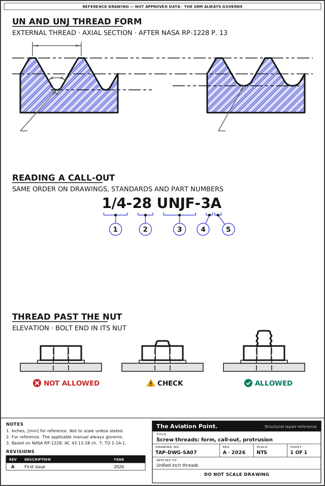
Common sizes and pitch, inch and mm
| Size | Fine series | Pitch, in (mm) | Coarse series | Pitch, in (mm) |
|---|---|---|---|---|
| No. 8 | 8-36 | 0.0278 (0.706) | 8-32 | 0.0313 (0.794) |
| No. 10 | 10-32 | 0.0313 (0.794) | 10-24 | 0.0417 (1.058) |
| 1/4 in (6.35 mm) | 1/4-28 | 0.0357 (0.907) | 1/4-20 | 0.0500 (1.270) |
| 5/16 in (7.94 mm) | 5/16-24 | 0.0417 (1.058) | 5/16-18 | 0.0556 (1.411) |
| 3/8 in (9.53 mm) | 3/8-24 | 0.0417 (1.058) | 3/8-16 | 0.0625 (1.588) |
| 7/16 in (11.11 mm) | 7/16-20 | 0.0500 (1.270) | 7/16-14 | 0.0714 (1.814) |
| 1/2 in (12.70 mm) | 1/2-20 | 0.0500 (1.270) | 1/2-13 | 0.0769 (1.954) |
| 9/16 in (14.29 mm) | 9/16-18 | 0.0556 (1.411) | 9/16-12 | 0.0833 (2.117) |
| 5/8 in (15.88 mm) | 5/8-18 | 0.0556 (1.411) | 5/8-11 | 0.0909 (2.309) |
| 3/4 in (19.05 mm) | 3/4-16 | 0.0625 (1.588) | 3/4-10 | 0.1000 (2.540) |
| 7/8 in (22.23 mm) | 7/8-14 | 0.0714 (1.814) | 7/8-9 | 0.1111 (2.822) |
| 1 in (25.40 mm) | 1-14 | 0.0714 (1.814) | — | — |
| 1-1/8 in (28.58 mm) | 1-1/8-12 | 0.0833 (2.117) | — | — |
| 1-1/4 in (31.75 mm) | 1-1/4-12 | 0.0833 (2.117) | — | — |
Size and TPI pairs as AC 43.13-1B Table 7-1 prints them (fine and coarse thread series); the coarse series stops at 7/8-9 there. Confirm the pitch of a 1 in part on its own standard. Pitch is calculated: 1 ÷ TPI in, 25.4 ÷ TPI mm.
The thread standards by number
| Standard | Title | Covers |
|---|---|---|
| ASME B1.1 | Unified Inch Screw Threads (UN and UNR Thread Form) | UNC, UNF, UNEF, UNR; classes 1A to 3A, 1B to 3B |
| ASME B1.15 | Unified Inch Screw Threads (UNJ Thread Form) | UNJ, industry standard |
| MIL-S-8879C, now SAE AS8879 | Screw Threads, Controlled Radius Root with Increased Minor Diameter (AS8879: UNJ Profile, Inch) | The aerospace UNJ thread |
| ASME B1.2 | Gages and Gaging for Unified Inch Screw Threads | Go and no-go thread gauges |
| NASM8846, ex MIL-I-8846 | Inserts, Screw-Thread, Helical Coil | Helical coil inserts |
2Allowable damage
Identifying and measuring a thread
| Check | How | Source |
|---|---|---|
| Threads per inch | Screw pitch gauge: the leaf that sits in the thread without light under it gives the TPI; with the size it names the series | AC 43.13-1B Table 7-1 (size and TPI pairs) |
| Pitch diameter | Thread micrometer, read like any micrometer | FAA-H-8083-30B ch. 11 (micrometer guide) |
| Fit to the class | Go and no-go thread gauges: plug gauge for an internal thread, ring gauge for an external one; acceptance by the gauging practice of the thread standard | ASME B1.2 |
| UNJ root radius | Mandatory and inspected; identify a UNJ part by its standard and part number | NASA RP-1228 p. 13 |
| Thread protrusion | Count the complete threads past the nut, chamfer included | TO 1-1A-1 par. 5.2.2.1; AC 43.13-1B par. 7-37 |
What the public documents accept and reject
| Case | Rule | Source |
|---|---|---|
| Bolt through a nut, FAA practice | At least one thread of the bolt protruding through a self-locking or plain nut | AC 43.13-1B par. 7-37 |
| Bolt through a nut, military practice | A minimum of two and a maximum of four complete threads, chamfer included, protrude through the nut; a slightly longer grip is allowed with a washer under the nut or head | TO 1-1A-1 par. 5.2.2.1 |
| Fiber or nylon locknut | At least one thread showing past the nut; not used above 250 °F (121 °C); not reused if it cannot meet the minimum prevailing torque (Table 7-2) | AC 43.13-1B par. 7-64f |
| Self-locking bolt (nylon pellet or strip) | Do not reuse | TO 1-1A-1 par. 5.2.2.12 |
| Overtorque | Overstresses the threaded areas and can fail the bolt or the nut | AC 43.13-1B par. 7-40 |
| Torque basis | Threads clean and dry unless the manufacturer specifies otherwise; Table 7-1 values are derived from oil-free cadmium-plated threads | AC 43.13-1B par. 7-40b, Table 7-1 |
| Weak, worn or stripped tapped thread | Repaired, not reused: insert, or threaded bushing when an insert cannot be used | TO 1-1A-1 par. 3.10a(1); NASA RP-1228 p. 10 |
| Substitution | Standard hex bolts are not substituted for internal wrenching or 12-point external wrenching bolts | TO 1-1A-1 pars. 5.2.2.6, 5.2.2.7 |
| Nicks, galling, cross-threading on a bolt or stud | — | The aircraft SRM, the AMM or the part's CMM; no generic public limit |
| UN and UNJ parts mixed | — | The drawing or the fastener standard decides |
Where AC 43.13-1B and TO 1-1A-1 differ (thread protrusion), the stricter rule or the aircraft's manual governs.
3Repair
Repairing a stripped tapped hole: the routes
| Route | How it holds | When | Source |
|---|---|---|---|
| Helical coil (wire thread) insert | A precision coil of diamond-section CRES wire, made slightly oversize for an interference fit in its tapped hole. The tang is broken off at the notch after installation; a locking version has a deformed coil | The most popular route for stripped threads: it needs the least hole enlargement | NASA RP-1228 p. 11 |
| Key-locking (solid bushing) insert | Conventional threads inside and out; the locking keys are driven in after the insert is in place | Preferred to the wire insert where space permits | NASA RP-1228 pp. 11-12 |
| Threaded bushing | Hole drilled out and retapped, bushing threaded to match, then tapped inside; pinned or staked in two places about 180° apart | When helical coil inserts cannot be used | TO 1-1A-1 par. 3.10 |
| Next thread size up | — | Changes the fastener: only with the drawing, the SRM or engineering approval | — |
Inserts in general: the insert's external thread is nominally 1/8 in (3.18 mm) bigger than its internal thread, so a 10-32 bolt works in what is in effect a 5/16-18 thread (NASA RP-1228 p. 10). Tap drill, tap and tang tool sizes come from the insert standard and its maker's data.
Threaded bushing: minimum wall after drilling and tapping
| Bolt, stud, plug or fitting OD up to | In aluminum, magnesium or brass | In steel |
|---|---|---|
| 1/2 in (12.7 mm) | 3/32 in, 0.0937 in (2.38 mm) | 1/10 in, 0.100 in (2.54 mm) |
| 3/4 in (19.05 mm) | 1/8 in, 0.125 in (3.18 mm) | 2/10 in, 0.200 in (5.08 mm) |
| 1-1/4 in (31.75 mm) | 3/16 in, 0.1875 in (4.76 mm) | 21/64 in, 0.3281 in (8.33 mm) |
| 2 in (50.8 mm) | 1/2 in, 0.500 in (12.7 mm) | 13/32 in, 0.4062 in (10.32 mm) |
TO 1-1A-1 par. 3.10b, as printed.
Threaded bushing: drilling, engagement and fit
| Item | Rule | TO 1-1A-1 |
|---|---|---|
| Drill before tapping | Equal to the smallest diameter of the tap threads, for full-depth threads | 3.10a(2) |
| Thread type | Pipe threads preferred where a pressure seal is required; standard threads otherwise | 3.10a(3) |
| Order | Thread the bushing OD to match the retapped hole; install it before tapping its ID, to avoid distortion | 3.10a(4) |
| Material | Chrome stainless, nickel steel or phosphor bronze for heavy or intermittent loads; final choice by load, dissimilar metals and other criteria | 3.10a(5) |
| Locking and sealing | Pinned or staked in two places about 180° apart; sealant on the outside threads under fluid pressure | 3.10a(6) |
| Threaded depth in the bushing | At least one bolt or stud diameter: 1/4 in (6.35 mm) for a 1/4 in bolt | 3.10c(1) |
| High stress, bushing in aluminum or magnesium | Engagement at least twice the bolt or stud diameter | 3.10c(2) |
| Lower stress, or harder and stronger parent metal | Engagement may be reduced proportionately | 3.10c(3) |
| Bushing without flange | Top face flush to 0.002 in (0.05 mm) below the boss surface | 3.10d |
Inserts and threaded bushings in section
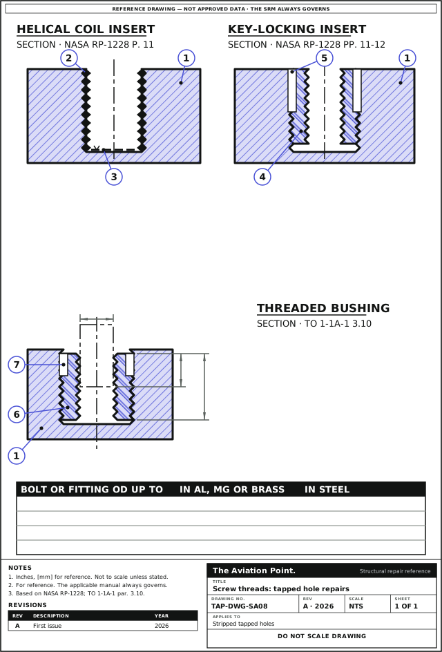
Step by step: a stripped tapped hole
| Step | Action | What to do |
|---|---|---|
| 1 | Identify the thread | Size, TPI, series and class from the drawing or the fastener's standard; confirm the TPI with a pitch gauge on the mating part, never on the damaged thread alone. |
| 2 | Get the repair authority | The SRM, the AMM, the CMM or the drawing says which insert or bushing the part accepts. A tapped hole is not taken to the next thread size without that approval. |
| 3 | Choose the route | Wire thread insert for the least enlargement; a key-locking (solid bushing) insert where space permits; a threaded bushing when helical coil inserts cannot be used (NASA RP-1228 pp. 11-12; TO 1-1A-1 par. 3.10). |
| 4 | Check what metal is left | For a bushing, the minimum wall by OD and parent metal (TO 1-1A-1 par. 3.10b). For an insert, the tapped-hole data of the insert standard. |
| 5 | Drill and tap | Tap drill equal to the smallest diameter of the tap threads. For a bushing: retap the hole, fit the bushing, then tap its bore (par. 3.10a(2) to (4)). |
| 6 | Install and lock | Wire insert: break the tang off at its notch. Key-locking insert: drive the keys. Bushing: pin or stake twice, 180° apart, seal it if it sees fluid pressure, and set it flush to 0.002 in below the boss. |
| 7 | Check and record | Gauge the finished thread go and no-go, check the engagement (one diameter, two in aluminum or magnesium under high stress), torque to the manual and record the repair on the work order. |
Thread lubricants and anti-seize
| Item | What the document says | Source |
|---|---|---|
| Default | Threads clean and dry unless the manufacturer specifies otherwise. A lubricated thread takes the torque its manufacturer gives, not Table 7-1, which is for oil-free cadmium-plated threads | AC 43.13-1B par. 7-40b, Table 7-1 |
| Wet installation | Often necessary during or after installation to help prevent corrosion | TO 1-1A-1 par. 5.2.2.3 |
| Oil or grease | Up to about 250 °F (121 °C); not in vacuum | NASA RP-1228 p. 4, table III |
| Graphite | Needs moisture (oil or water) to lubricate, so it is limited to the carrier's boil-off, 212 to 250 °F (100 to 121 °C); abrasive beyond that | NASA RP-1228 p. 4, table III |
| Molybdenum disulfide | A popular dry lubricant, usable in vacuum; at about 750 °F (399 °C) it turns into molybdenum trisulfide, an abrasive | NASA RP-1228 p. 4 |
| MoS2 coating on locknuts | Clean, dry, bonded coating that prevents seizing and galling of threads | AC 43.13-1B par. 7-65d |
| Silver plating on locknuts | For heat, to 1,400 °F (760 °C); resists galling and seizing under heat or heavy pressure | AC 43.13-1B par. 7-65b |
| Thread-locking compound | Some, chiefly the removable grades, also act as lubricants for a bolted joint | NASA RP-1228 p. 4 |
| Anti-seize compound | — | Only where the AMM, the CMM or the drawing calls for it, with the torque it gives |
Worked example: a 1/4-28 stud in an aluminum boss
A highly stressed 1/4-28 stud has stripped its tapped hole in an aluminum boss. The SRM accepts a threaded bushing and no helical coil insert can be used.
- Stud OD 1/4 in falls in the up to 1/2 in row: minimum wall after drilling and tapping in aluminum 3/32 in (0.0937 in, 2.38 mm) (par. 3.10b(1)).
- Threaded depth in the bushing: at least one diameter, 1/4 in (6.35 mm) (par. 3.10c(1)).
- High stress in aluminum: engagement at least twice the diameter, 1/2 in (12.7 mm) (par. 3.10c(2)). This governs.
- Bushing: chrome stainless, nickel steel or phosphor bronze; its OD thread matches the retapped hole; tapped 1/4-28 inside after installation (par. 3.10a(4), (5)).
- Locking: pinned or staked in two places about 180° apart; no flange, so set flush to 0.002 in (0.05 mm) below the boss face (par. 3.10a(6), d).
Quick check
A threaded bushing in aluminum carries a highly stressed stud. How much thread engagement does TO 1-1A-1 ask for?
- At least twice the stud diameter
Best fit. Yes: par. 3.10c(2), for high stress in aluminum or magnesium.
- One stud diameter
Not this one. No: that is the minimum threaded depth in any bushing, par. 3.10c(1).
- Two to four complete threads
Not this one. No: that is thread protrusion through a nut, par. 5.2.2.1.
On a real job, the SRM decides.
Questions people actually ask
Why are aircraft bolts mostly fine thread?
UNF has a larger minor diameter than UNC, which gives slightly more load-carrying and better torque-locking, tighter tolerances and a smaller lead angle for finer adjustment; it is the most widely used thread in aerospace (NASA RP-1228 p. 12).
How many threads must show past the nut?
AC 43.13-1B par. 7-37: at least one. TO 1-1A-1 par. 5.2.2.1: two to four complete threads, chamfer included. Work to the stricter one unless the aircraft's manual says otherwise.
Can a UNJ bolt take a UN nut?
The public documents read give no interchange rule: the drawing or the fastener standard decides. What they do say is that the J root radius is mandatory and inspected, and that bolts above 180 ksi (1,241 MPa) usually have it (NASA RP-1228 p. 13).
Helical coil or key-locking insert?
The wire thread insert needs the least enlargement and is the most popular for stripped threads; a solid bushing insert, such as a key-locking one, is preferred where space permits (NASA RP-1228 pp. 11-12). The SRM or the drawing names the one the part accepts.
Do I oil the threads before torquing?
Not unless the manufacturer says so: AC 43.13-1B par. 7-40b asks for clean, dry threads, and Table 7-1 is derived from oil-free cadmium-plated threads. With a lubricant, use the torque that goes with it.
Limits of this guide
What the sources support, and no further.
- The SRM governs. Every rule here is what a public document prints; the aircraft's SRM, AMM or CMM overrides it.
- No generic limit for nicks, galling or cross-threading of an external thread is published in the documents used.
- Thread dimensions and gauge tolerances are in ASME B1.1, B1.2, B1.15 and AS8879; they are not reproduced.
- Insert tapped-hole, tap and tooling data come from the insert standard and its maker; they are not reproduced.
Where to buy
Are you a distributor? Get listed →
Distributors coming soon.
Keep going
Calculators
Guides
How to do it
Tools
Data sheets
Books
Buy
Distributors coming soon.
Main sources
- AC 43.13-1B CHG 1, Acceptable Methods, Techniques, and Practices: Aircraft Inspection and Repair — Par. 7-14a (screws); 7-37 (thread protrusion); 7-40, 7-40b and Table 7-1 (torque, thread sizes); 7-64e, f (self-locking nuts); 7-65b, d (silver plating, molybdenum disulfide).
- NASA Reference Publication 1228, Fastener Design Manual, R. T. Barrett, March 1990 — P. 4 and table III (thread lubricants); pp. 10 to 12 (inserts); pp. 12, 13 (thread types, classes of threads, forming of threads).
- TO 1-1A-1 / NAVAIR 01-1A-1, General Manual for Structural Repair (15 Jan 2016) — Par. 3.10 (repair of threaded installations); 5.2.2.1, 5.2.2.3, 5.2.2.6, 5.2.2.7, 5.2.2.12 (bolts).
- FAA-H-8083-30B, Aviation Maintenance Technician Handbook: General (2023), chapter 11 — Thread micrometer, through the micrometer guide.
- Thread and insert standards named by number — ASME B1.1, ASME B1.2, ASME B1.15, MIL-S-8879C and SAE AS8879, NASM8846: named as what governs; not reproduced.
Cross-checked with other manuals and standards in our library.