1Identification
Where to buyScrews by number
| Group | Standards | Use | Source |
|---|---|---|---|
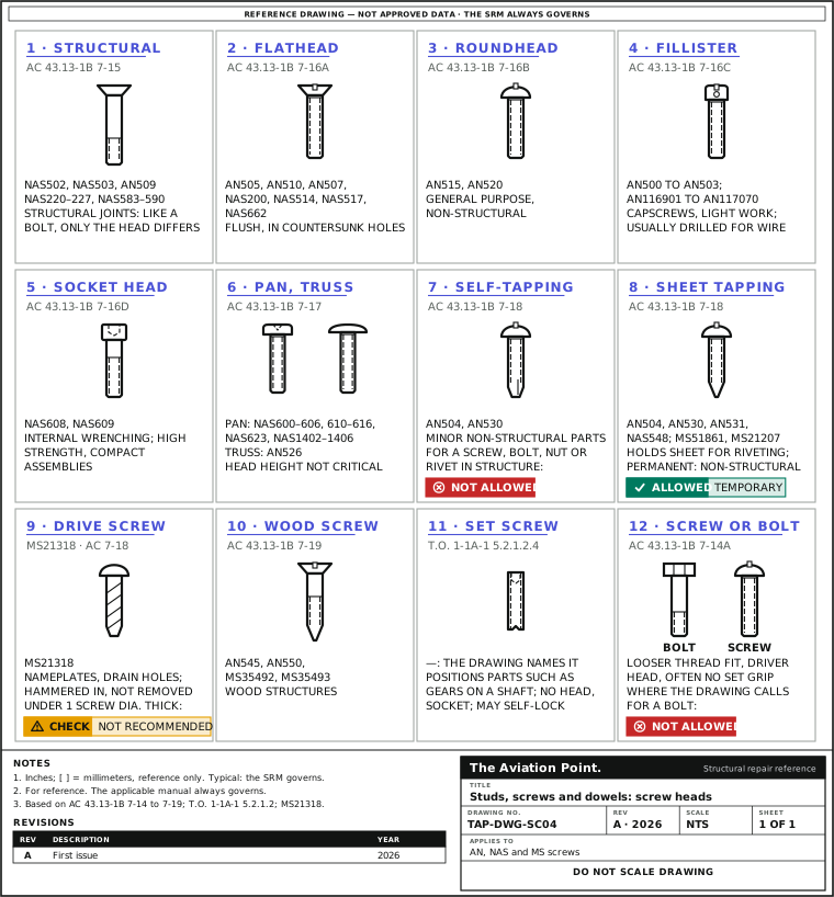
| Structural screws | NAS502, NAS503, AN509, NAS220 to NAS227, NAS583 to NAS590 | Structural joints, like structural bolts or rivets: high-tensile material, only the head differs from a bolt | AC 43.13-1B 7-15 |
| Flathead machine screws | AN505, AN510, AN507, NAS200, NAS514, NAS517, NAS662 (data sheets: AN505, AN507, AN510) | Countersunk holes where a flush surface is wanted | 7-16a |
| Roundhead machine screws | AN515, AN520 | General purpose, non-structural | 7-16b |
| Fillister head machine screws | AN500 to AN503 and the AN116901 to AN117070 ranges | Capscrews in light mechanical work; usually drilled for safety wire | 7-16c |
| Socket head machine screws | NAS608, NAS609 | Internal wrenching; high strength, compact assemblies, heads sunk into fitted holes | 7-16d; T.O. 1-1A-1 5.2.1.2.2.4 |
| Panhead and truss head | NAS600 to NAS606, NAS610 to NAS616, NAS623, NAS1402 to NAS1406; truss head AN526 | General purpose where head height does not matter | AC 43.13-1B 7-17 |
| Self-tapping machine screws | AN504, AN530 | Minor non-structural parts | 7-18 |
| Self-tapping sheet metal screws | AN504, AN530, AN531, NAS548; also MS51861, MS21207 (data sheets) | Blind, temporary attachment of sheet for riveting; permanent assembly of non-structural parts | 7-18; data sheets |
| Drive screws | MS21318 | Nameplates and sealing drain holes; driven with a hammer, not meant to come out | 7-18 |
| Wood screws | AN545, AN550, MS35492, MS35493 | Wood structures | 7-19 |
| Set screws | —: the drawing names them | Position parts such as gears on a shaft; socket instead of a head; may be self-locking | T.O. 1-1A-1 5.2.1.2.4 |
Marking: as the AN, NAS or MS drawing requires; the maker normally puts his trademark on the head (AC 43.13-1B 7-14a). Design data: MIL-HDBK-5 (7-14b).
Screw heads by family
Studs and pins
| Item | Standard or document | What it does | Source |
|---|---|---|---|
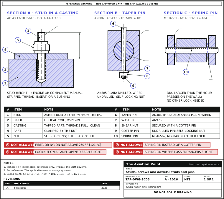
| Stud | Continuous thread, double-end and flange bolting studs: ASME B18.31.2 (inch). Aircraft studs: the IPC or drawing gives the part number | Threaded rod that stays in a tapped part (casting, crankcase, fitting); the nut on the free end clamps | ASME B18.31.2 title |
| Cylinder hold-down stud | —: the engine maker's part number | Fiber-insert locknuts on these studs are approved only in a few instances and not generally recommended: tight stud fit to the crankcase and good cooling are needed | AC 43.13-1B 8-9 |
| Taper pin | AN385 plain, AN386 threaded; MS24692 | Shear joints where the absence of play is essential | 7-101 |
| Flathead (clevis) pin | AN392 to AN406 | Tie-rod terminals and secondary controls not in continuous operation | 7-102 |
| Spring pin | MS16562, MS9048 | Double shear; diameter larger than the hole, so it presses on the hole wall; needs no other securing | 7-104 |
| Dowel pin | MIL-P-21143 (straight headless dowel pins, general specification); ASME B18.8.2 (inch pins); MS9105 straight headless lock pin | Locates mating parts; fit and size from the drawing | Standard titles; MS9105 Rev. B |
No public general rule for stud setting height, driving torque or oversize steps was found: the engine or component manual sets them.
Studs and pins in section
May it go there?
| Case | Status | Source |
|---|---|---|
| Self-tapping screw in place of a standard screw, nut, bolt or rivet in any aircraft structure | NOT ALLOWED | AC 43.13-1B 7-18, caution |
| Self-tapping sheet metal screw to hold sheet temporarily for riveting | ALLOWED | 7-18 |
| Drive screw in material thinner than one screw diameter | CHECK: not recommended by the standard | MS21318 Rev. A, note |
| Self-locking nut on a stud or screw holding a panel opened before or after each flight | NOT ALLOWED | 7-64d |
| Fiber or nylon locknut where the temperature exceeds 250 °F (121 °C) | NOT ALLOWED | 7-64f |
| Speed nut with self-tapping screws | ONLY where it was used in the original assembly | 7-72 |
| Spring pin where its loss or failure might endanger safe flight | NOT ALLOWED | 7-104a |
| Spring pins mixed with other structural fasteners in one joint | NOT ALLOWED | 7-104b |
| Spring pin as a substitute for a cotter pin | NOT ALLOWED | 7-104c |
2Allowable damage
Inspection and acceptance
| Check | Accept | Reject or act | Source |
|---|---|---|---|
| Thread past a self-locking nut on a bolt or stud | At least one thread showing | Fit the length the IPC calls for | AC 43.13-1B 7-64f |
| Prevailing torque of a self-locking nut | At or above the minimum of AC table 7-2 (values on Torquing) | Below it: replace the nut | 7-64f, 7-122c |
| Tapped hole for a stud or screw | Full, clean threads | Weak, worn or stripped: helical coil insert, or a threaded bushing where an insert cannot be used | T.O. 1-1A-1 3.10 |
| Spring pin and its hole | No deformation of pin or hole | Pin gap closed by misalignment, or excess force to insert: do not use the pin | 7-104b, c |
| Magnetic particle check of steel studs and screws | —: the NDT manual sets the acceptance | Thread roots, keyways and drilled holes can give nonrelevant indications: confirm before rejecting | 5-40b(2) |
| Drive screw | In place | Not made to be removed: replacement as the drawing or SRM says | 7-18 |
| Stud height, run-out, looseness | — | —: the engine or component manual sets the limits | — |
3Repair
Fitting and removal
| Step | Action | What to do |
|---|---|---|
| 1 | Identify | Take the number from the IPC or drawing. Screws carry the marking the AN, NAS or MS drawing requires (AC 43.13-1B 7-14a). Never fit a screw where a bolt is called for. |
| 2 | Check the tapped hole | Look at the threads before a stud or screw goes in. Weak, worn or stripped threads get a helical coil insert or, where an insert cannot be used, a threaded bushing (T.O. 1-1A-1 3.10); see the MS21209 and MS51830 data sheets. |
| 3 | Stud | Drive and set it as the engine or component manual says (height, torque, sealant). No general figure is published. |
| 4 | Nut on a stud | Self-locking nut: at least one thread past the nut (7-64f). Castellated nut to be wired: tighten to the low side of the torque range, then on until a slot lines up (7-126). |
| 5 | Self-tapping screw | Drill or punch the hole slightly smaller than the screw; the screw taps its own thread (7-18). Hole size: the screw standard or the maker's chart. |
| 6 | Drive screw | Drive it with a hammer into a drilled hole (7-18), in material at least one screw diameter thick (MS21318 note). |
| 7 | Taper pin | Plain AN385: drilled and secured with wire. Threaded AN386: AN975 washer and a shear nut with a cotter pin, or a self-locking nut if undrilled (7-101, 7-89). |
| 8 | Spring or clevis pin | Spring pin: into a hole that is not enlarged or misaligned; no other lock needed (7-104). Clevis pin: head up or forward, so it stays if the cotter pin fails (7-102). |
Worked example: a bracket near an exhaust
A stud-mounted bracket next to an exhaust pipe runs at 300 °F (149 °C); the reading is made up for the example. The IPC calls for a self-locking nut.
- Fiber or nylon locknuts are not installed where the temperature exceeds 250 °F (121 °C) (AC 43.13-1B 7-64f).
- 300 °F is above 250 °F: an all-metal locknut, the type used in high-temperature areas (7-64e), or the nut the IPC names for that position.
- After torquing, at least one thread shows past the nut (7-64f).
- On a cylinder hold-down stud, a fiber-insert nut is not generally recommended even where it was once approved (8-9).
All-metal self-locking nut, one thread past, torque from the manual.
Quick check
A non-structural fairing lost a screw. The only one in the drawer that fits is an AN530 self-tapping screw. The fairing is held by AN515 machine screws into nutplates. What do you do?
- Fit the AN530: the fairing is non-structural.
Not this one. A self-tapping screw never replaces a standard screw (AC 43.13-1B 7-18, caution), and it would cut into the nutplate thread.
- Fit the AN515 the IPC calls for, into the nutplate.
Best fit. Same part, same thread: the original assembly is restored.
- Drill the hole out and fit a drive screw.
Not this one. Drive screws are for nameplates and drain holes and are not meant to be removed (7-18); a fairing comes off.
On a real job, the SRM decides.
Questions people actually ask
Screw or bolt: how do I tell them apart on the drawing?
By the standard number. Screws usually have lower material strength, a looser thread fit, a driver head and may be threaded full length with no clear grip (AC 43.13-1B 7-14a). Structural screws (7-15) are the exception: bolt strength with a screw head.
Where are the stud setting heights and torques?
In the engine or component manual for that stud. No public general table was found, so this page shows «—» and names who sets them.
Can I reuse a spring pin?
Yes, if careful inspection shows no deformation of the pin or the hole (AC 43.13-1B 7-104b). Not if the hole is enlarged or misaligned (7-104c).
Which threads are on these screws?
The screw standard sets them. Thread classes and series are a subject of their own (EASA 6.5.1).
Limits of this guide
What the sources support, and no further.
- The manual governs. The IPC, drawing, SRM and component manual come before AC 43.13-1B.
- Studs: no public general data was found for setting height, driving torque or oversize studs; «—» stays until a public source gives them.
- Standards are named by number and title; their dimensions are on the data sheets linked, or in the standard itself.
- Bolts and nuts are covered on their own pages and data sheets.
Where to buy
Are you a distributor? Get listed →
Distributors coming soon.
Keep going
Calculators
Guides
How to do it
Data sheets
Books
Buy
Distributors coming soon.
Main sources
- FAA AC 43.13-1B CHG 1, Acceptable Methods, Techniques, and Practices: Aircraft Inspection and Repair — Pars. 7-14 to 7-19 (screws, table 7-11); 7-64 (self-locking nuts); 7-72 (sheet spring nuts); 7-89 (taper pin washers); 7-101, 7-102, 7-104 (pins); 7-122c; 7-126 (castellated nuts on studs); 8-9 (cylinder hold-down studs); 5-40b(2) (nonrelevant indications).
- T.O. 1-1A-1 / NAVAIR 01-1A-1, General Manual for Structural Repair — 5.2.1.2.2.4 socket head screws; 5.2.1.2.3 self-tapping screws; 5.2.1.2.4 set screws; 3.10 repair of threaded installations.
- MS21318 Rev. A, Screw, Drive, Round Head, Type U — Note: not recommended in material thinner than one screw diameter.
- MIL-P-21143, Pin, Straight, Headless (Dowel), General Specification for — Named by number and title.
- ASME B18.8.2, Taper Pins, Dowel Pins, Straight Pins, Grooved Pins, and Spring Pins (Inch Series) — Named by number and title.
- ASME B18.31.2, Continuous Thread Stud, Double-End Stud, and Flange Bolting Stud (Stud Bolt) (Inch Series) — Named by number and title.
Cross-checked with other manuals and standards in our library.