1Identification
Where to buyThe words on the drawing
| Term | Meaning | Source |
|---|---|---|
| Basic size | The size the limits are applied to | ANSI B4.1; ISO 286-1 |
| Limits and tolerance | Largest and smallest acceptable size; the tolerance is their difference. 0.225 +0.0025 −0.0005: limits 0.2275 and 0.2245, tolerance 0.0030 in (0.076 mm) | FAA-H-8083-30B ch. 4, Tolerances |
| Allowance | The intended difference between the mating parts at their maximum material: the tightest condition of the fit | ANSI B4.1 |
| Clearance fit | The hole is always larger than the shaft | ANSI B4.1; ISO 286-1 |
| Transition fit | Clearance or interference, depending on the actual sizes | ANSI B4.1; ISO 286-1 |
| Interference fit | The shaft is always larger than the hole; the parts are pressed, driven or shrunk together | ANSI B4.1; ISO 286-1 |
| Hole basis | The hole keeps its basic size as its lower limit and the shaft is varied for each fit (ISO H holes) | ISO 286-1 |
| Shaft basis | The shaft keeps its basic size as its upper limit and the hole is varied (ISO h shafts) | ISO 286-1 |
The common systems of fits
| System | How a fit is written | Values |
|---|---|---|
| ISO 286 (metric) | Hole letter and grade over shaft letter and grade, e.g. H7/g6: the letter places the tolerance zone, the number (IT grade) sets its width | — (ISO 286-2 tables) |
| ANSI inch classes | ANSI B4.1: RC1 to RC9 running and sliding, LC1 to LC11 locational clearance, LT1 to LT6 locational transition, LN1 to LN3 locational interference, FN1 to FN5 force and shrink | — (ANSI B4.1 tables) |
| NAS618 (fastener holes) | Hole columns for each pin: A minimum clearance, G transition, F interference; J and R for the oversize pins. The drawing picks the column | Per pin in Hi-Lok holes |
| Aircraft drawings | Mostly the two limits written out, or a fit named in a note: light-drive fit, interference fit | AC 43.13-1B par. 7-39; the drawing |
The drawing or the SRM names the fit. This page does not convert one system into another.
Fits on bolt and fastener holes
| Fit | What is published | Source |
|---|---|---|
| AN bolt in a normal hole | First lettered drill above the nominal bolt diameter: fastener hole drill | AC 43.13-1B par. 7-39 |
| Light-drive fit (reamed) | AN hex bolts in reamed holes, NAS close-tolerance bolts and AN clevis bolts: not the letter drill. A light-drive fit is an interference of 0.0006 in (0.015 mm) for a 5/8 in bolt | AC 43.13-1B par. 7-39 |
| Bolts in a longeron repair | Bolt holes drilled for a light-drive fit | FAA-H-8083-31B p. 4-103 |
| Hi-Lok and Hi-Tigue | Interference in aluminum, not over 0.002 in (0.05 mm); clearance in steel, titanium and composite | FAA-H-8083-31B p. 4-50 |
| Solid rivets | Hole just over the shank; the driven rivet fills it: rivet drill sizes | FAA-H-8083-31B Fig. 4-90 |
| Worn or oversize holes | Next size, reaming and bushings: fastener hole damage | AC 43.13-1B par. 7-39; the SRM |
Drill charts: drill sizes. Each figure here is the only one its document prints; the drawing or the SRM governs.
The schedule of fits and clearances: the table of limits
| Where | What it gives | Source |
|---|---|---|
| Engines | The engine maker's manuals and table of limits; a crankshaft bent beyond the maker's permissible service limit is replaced | AC 43.13-1B pars. 8-1, 8-2g(2), 8-3 |
| Components | Bushings, bearings, hinge pins, actuators: the component maintenance manual (CMM) of the part, in its fits and clearances section | ATA iSpec 2200 (CMM); the maker's CMM |
| Structure | Hole and fastener fits on the drawing or in the SRM; a worn hole is hole damage | AC 43.13-1B par. 7-39; the SRM |
TAP reproduces no maker's table of limits: it belongs to the maker's manual, and its revision governs.
2Allowable damage
Bow, twist and wear: what is published
| Part | Published rule | Limit | Source |
|---|---|---|---|
| Crankshaft | Replace if bent beyond the maker's permissible service limit. Worn journals reground to the maker's instructions; fillet radii never reduced; nitrided shafts re-nitrided where the maker says so | — (maker's table of limits) | AC 43.13-1B par. 8-3 |
| Crankshaft flange before tear-down | Inspected for twisting, cracks or other deformation; the shaft turned slowly in 90° steps under a dial indicator to check its concentricity | — (maker) | AC 43.13-1B par. 8-2c(3), (4) |
| Accessory drive couplings | Twisted splines, misalignment and run-out | — (maker) | AC 43.13-1B par. 8-2d(2)(c) |
| Connecting rods | Cracks and straightness | — (maker) | AC 43.13-1B par. 8-2d(2)(d) |
| Gears and damper pins | Cracked, broken or brinelled teeth; nicks or brinelling on damper pins and liners | — (maker) | AC 43.13-1B par. 8-2d(1), (2)(b) |
| Engine mount | Bent, cracked or buckled tubes; flex mounts for looseness, distortion or wear | — (maker) | AC 43.13-1B par. 8-2f(1), (2) |
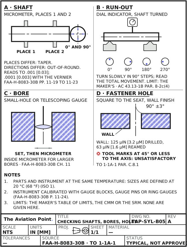
| Fastener holes | Square to the seat face; wall finish; tool marks at 45° or less to the hole axis unsatisfactory; heat discoloration to engineering | ±3° · 125 µin (3.2 µm) drilled · 63 µin (1.6 µm) reamed | TO 1-1A-1 par. C.8.1 |
No public document gives a generic bow, twist or wear value for these parts: the maker's table of limits sets each one, and «—» marks it.
Standard methods for checking shafts, bores and holes
| Check | Method | Source |
|---|---|---|
| Shaft diameter | Outside micrometer, read to 0.001 in (0.0001 in with the vernier); several places along and round the shaft show taper and out-of-round | FAA-H-8083-30B pp. 11-19 to 11-23 |
| Bore or bushing | Telescoping or small-hole gauge set in the bore, then measured with the micrometer; inside micrometer for larger bores | FAA-H-8083-30B ch. 11 |
| Run-out and concentricity | Dial indicator on the shaft while it is turned slowly; read the total movement | AC 43.13-1B par. 8-2c(4) |
| Gap between parts | Thickness (feeler) gauge, e.g. 0.005 in (0.13 mm) under a blind rivet head | FAA-H-8083-31B p. 4-40 |
| Bearings | Play, roughness and rejection: the bearing or component maker's data | — (the CMM) |
| Holes | Calibrated precision measuring equipment for diameter, location, edge distance, roundness and taper; a surface finish gauge for the wall | TO 1-1A-1 par. C.8.1 b, d, e |
| The instrument | Calibrated to its maker's instructions with gauge blocks, gauge pins or ring gauges | FAA-H-8083-30B p. 11-24 |
Parts and instrument at the same temperature: dimensions are defined at the standard reference temperature of ISO 1.
3Repair
Checking a fit, step by step
| Step | Action | What to do |
|---|---|---|
| 1 | Find the limits | The drawing for a new part, the table of limits for a part in service: hole, shaft and fit, at the current revision. |
| 2 | Clean and settle | Parts and instrument clean and at the same temperature. |
| 3 | Check the instrument | Zero it against its standard (FAA-H-8083-30B p. 11-24). |
| 4 | Measure the hole | At several depths and in two directions at right angles: note the largest and the smallest. |
| 5 | Measure the shaft | The same way, over the length that engages. |
| 6 | Work out the fit | Hole minus shaft: positive is clearance, negative is interference. Compare with the limits. |
| 7 | Out of limits | The maker's repair: oversize or undersize part, bushing, regrind, or replace. Holes: fastener hole damage. |
| 8 | Record | Measured values, limits, and the document and revision used (14 CFR 43.9(a)(1)). |
Worked example: three fits on one Hi-Lok pin
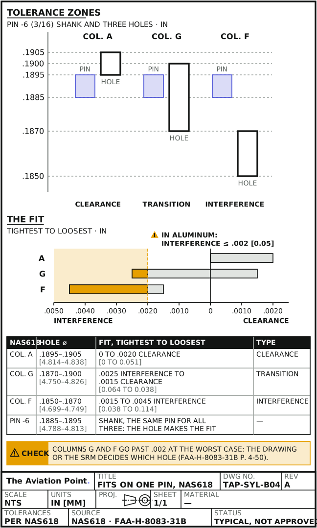
A -6 (3/16 in) Hi-Lok pin has a shank of 0.1885 to 0.1895 in. NAS618 gives three hole bands for it: column A 0.1895 to 0.1905, column G 0.1870 to 0.1900 and column F 0.1850 to 0.1870 in (listed in the Hi-Lok holes guide). Which fit does each give?
- Column A. Tightest: 0.1895 − 0.1895 = 0. Loosest: 0.1905 − 0.1885 = 0.0020 in clearance (0.051 mm). Never interference: a clearance fit.
- Column G. Tightest: 0.1870 − 0.1895 = −0.0025, that is 0.0025 in interference (0.064 mm). Loosest: 0.1900 − 0.1885 = 0.0015 in clearance (0.038 mm). Either way: a transition fit.
- Column F. Loosest: 0.1870 − 0.1885 = −0.0015. Tightest: 0.1850 − 0.1895 = −0.0045. Always interference, 0.0015 to 0.0045 in (0.038 to 0.114 mm).
- In aluminum the interference must not exceed 0.002 in (FAA-H-8083-31B p. 4-50). At the worst case column G reaches 0.0025 in and column F 0.0045 in: the drawing or the SRM decides which hole applies.
A is a clearance fit (0 to 0.0020 in), G a transition fit (0.0025 in interference to 0.0015 in clearance), F an interference fit (0.0015 to 0.0045 in). The pin did not change: the hole made the fit.
Restoring a fit
| Condition | Repair route | Source |
|---|---|---|
| Oversize or elongated bolt hole | Ream or drill for the next larger bolt may be permissible, keeping edge distance, clearance and structural integrity; consult the SRM, the maker or the authority before working a critical member | AC 43.13-1B par. 7-39 |
| Worn crankshaft journals | Regrind to the maker's instructions, preferably by an appropriately rated repair station or the maker; polish out tool marks; do not reduce fillet radii | AC 43.13-1B par. 8-3 |
| Crankshaft bent beyond the service limit | Replace | AC 43.13-1B par. 8-3 |
| Replacement parts in a certificated engine | Approved parts only: from the maker, an authorized facility, PMA or TSO, meeting 14 CFR part 21 | AC 43.13-1B par. 8-4 |
Quick check
A pin is 0.1885 to 0.1895 in and its hole 0.1870 to 0.1900 in. What fit is it?
- Transition
Best fit. Yes: from 0.0025 in interference to 0.0015 in clearance.
- Clearance
Not this one. The smallest hole is smaller than the largest pin.
- Interference
Not this one. The largest hole is larger than the smallest pin.
On a real job, the SRM decides.
Questions people actually ask
What is the difference between tolerance and allowance?
Tolerance is the spread allowed on one part. Allowance is the intended difference between two mating parts at their tightest condition (ANSI B4.1).
What is a light-drive fit?
AC 43.13-1B par. 7-39 defines it as an interference of 0.0006 in for a 5/8 in bolt, for AN hex bolts in reamed holes. No other size is printed there; the drawing or the SRM gives the hole.
Can I use an H7/g6 fit on an aircraft part?
Only if the drawing calls it up. The fit is the designer's choice, written on the drawing; the mechanic works to it.
Where are the wear limits of an engine part?
In the engine maker's table of limits, part of its inspection and overhaul data (AC 43.13-1B pars. 8-2g, 8-3). TAP does not reproduce it.
Why measure in two directions?
One reading cannot show out-of-round or taper. The difference between readings at right angles, and along the length, does.
Limits of this guide
What the sources support, and no further.
- The maker's manual governs: table of limits, CMM, SRM and drawing, at their current revision.
- No ISO 286 or ANSI B4.1 values are printed: their tables are not public. The class names are given so a drawing can be read.
- No generic bow, twist or wear value is published for the parts on this page; «—» marks it.
- Light-drive fit: AC 43.13-1B prints one figure, for a 5/8 in bolt only.
- Engine work is shown only for the checks AC 43.13-1B names; an overhaul is done to the engine maker's manual.
Where to buy
Are you a distributor? Get listed →
Distributors coming soon.
Keep going
Calculators
Guides
How to do it
Tools
Data sheets
Books
Buy
Distributors coming soon.
Main sources
- FAA AC 43.13-1B CHG 1 — Par. 7-39, bolt fit and light-drive fit, oversize holes; 8-1, the engine maker's data; 8-2c, d, f, g, special inspection (dial indicator, run-out, straightness, brinelling, table of limits); 8-3, crankshaft service limit and regrinding; 8-4, approved replacement parts.
- FAA-H-8083-31B, Aviation Maintenance Technician Handbook: Airframe — P. 4-40, feeler gauge under a blind rivet head; p. 4-50, Hi-Lok and Hi-Tigue fits; p. 4-103, light-drive fit for bolts in a longeron repair; Fig. 4-90, rivet drills.
- FAA-H-8083-30B, Aviation Maintenance Technician Handbook: General (2023) — Ch. 4, tolerances; pp. 11-19 to 11-24, micrometers and their calibration; ch. 11, telescoping and small-hole gauges.
- TO 1-1A-1 (NAVAIR 01-1A-1), General Aircraft Structural Repair — Par. C.8.1, hole squareness, inspection, surface finish and calibrated measuring equipment.
- NAS618 — Hole columns A, G, F, J and R, as listed in the Hi-Lok holes guide.
- ANSI B4.1-1967, Preferred Limits and Fits for Cylindrical Parts — Terms and the RC, LC, LT, LN and FN classes; values not reproduced.
- ISO 286-1, Geometrical product specifications (GPS): ISO code system for tolerances on linear sizes, Part 1 — Fit types, hole-basis and shaft-basis systems; ISO 286-2 values not reproduced.
- ISO 1, Geometrical product specifications (GPS): Standard reference temperature — Standard reference temperature: named as what governs, not reproduced.
- ATA iSpec 2200 — Component maintenance manual: fits and clearances section.
- 14 CFR 43.9 — (a)(1), reference to the data used, in the record.
- Regulation (EU) No 1321/2014, Annex III (Part-66), Appendix I, as amended by Regulation (EU) 2023/989 — Module 7.6, syllabus wording.
- FAA-S-ACS-1, Aviation Mechanic General, Airframe, and Powerplant Airman Certification Standards — AM.I.E and AM.I.K, related subjects.
Cross-checked with other manuals and standards in our library.