1Identification
Where to buy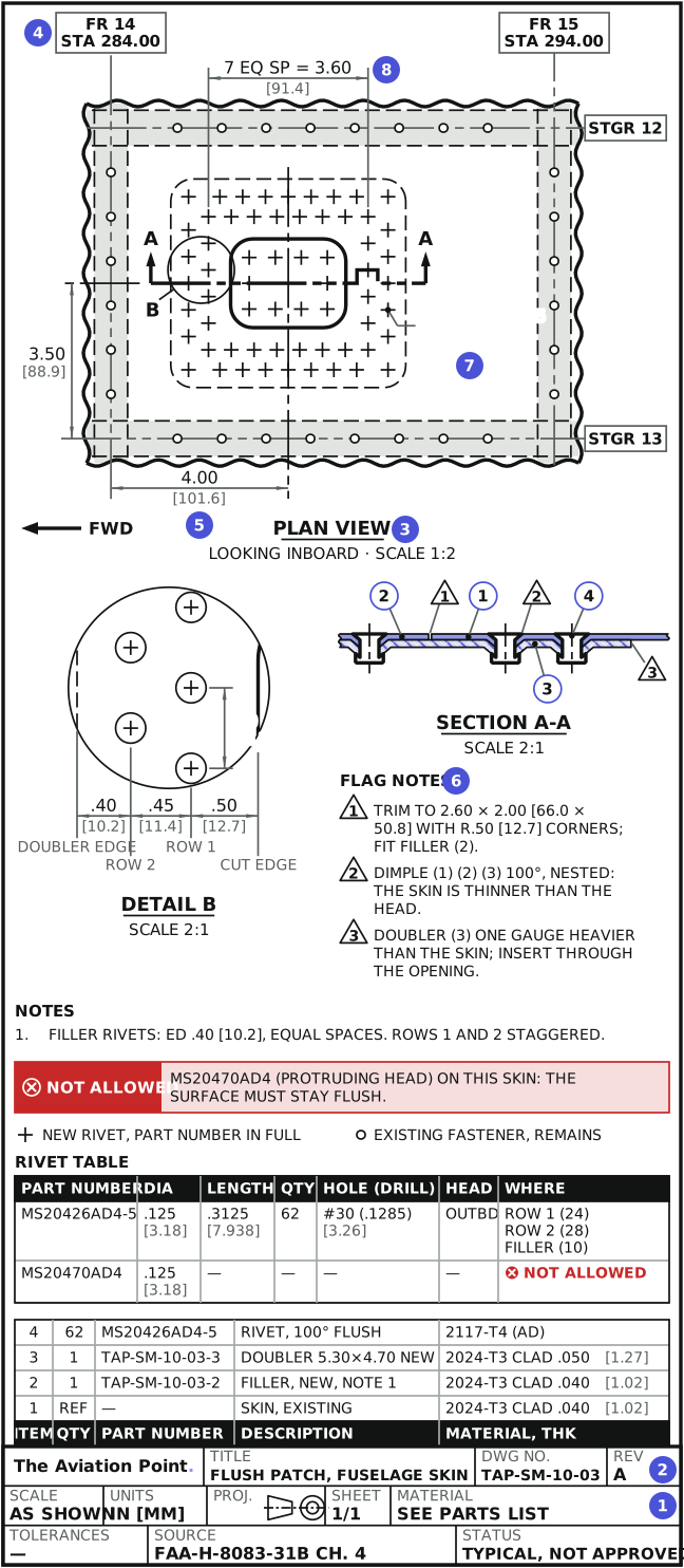
Drawing types and diagrams
| Type | What it shows | Source |
|---|---|---|
| Detail | One part: shape, sizes, material and how it is made. Several small details may share one sheet | FAA-H-8083-30B ch. 4, Types of Drawings |
| Assembly | Two or more parts joined; each part carries an item number in a circle, keyed to the bill of material | FAA-H-8083-30B ch. 4, Types of Drawings; Bill of Material |
| Installation | A part or an assembly in its final position on the aircraft, with the dimensions that locate it from other parts | FAA-H-8083-30B ch. 4, Types of Drawings |
| Sectional view | The part cut by a cutting plane to show the inside: full, half, revolved and removed sections | FAA-H-8083-30B ch. 4, Sectional View Drawings |
| Exploded view | The parts drawn apart along their assembly line, showing how they go together | FAA-H-8083-30B ch. 4, Types of Drawings |
| Diagrams | Block, schematic, wiring and installation diagrams and flowcharts: how a system works or is wired, not the shape of a part | FAA-H-8083-30B ch. 4; Part-66 7.5 |
Title block and revision block
| Field | What it tells you | Source |
|---|---|---|
| Drawing number | Identifies the print; in the number block at the lower right of the title block. On a drawing of several sheets: the sheet number and the total | FAA-H-8083-30B ch. 4, Drawing or Print Numbers |
| Dash number | Variants of one part on one drawing. “470204-1LH shown; 470204-2RH opposite”: the left part is drawn, the right one is its mirror image. Some systems use odd dashes for left, even for right | FAA-H-8083-30B ch. 4, Reference and Dash Numbers |
| Reference numbers | Other drawings that belong with this one | FAA-H-8083-30B ch. 4, Reference and Dash Numbers |
| Title and signatures | Name of the part or assembly, the scale, the date, the company, and who drew, checked and approved it | FAA-H-8083-30B ch. 4, Title Blocks |
| General tolerances | Apply to every dimension that carries no tolerance of its own | FAA-H-8083-30B ch. 4, Tolerances |
| Projection symbol | Third angle or first angle: where each view sits (see Views) | ASME Y14.3; ISO 5456-2 |
| Material and finish | Specification, temper and thickness, in the parts list on an assembly; finish marks give the surface condition | FAA-H-8083-30B ch. 4, Bill of Material; Finish Marks |
| Revision block | Ruled columns near the title block: revision symbol, date and description of each change | FAA-H-8083-30B ch. 4, Revision Block |
Read the units line before the first dimension. TAP drawings carry it as a note: DIMENSIONS IN INCHES. [ ] = MILLIMETERS, REFERENCE ONLY.
Views and projection
| Item | How to read it | Source |
|---|---|---|
| Orthographic views | Each view looks square at one face: front, top, side. Simple parts need one or two views; most need three | FAA-H-8083-30B ch. 4, Orthographic Projection |
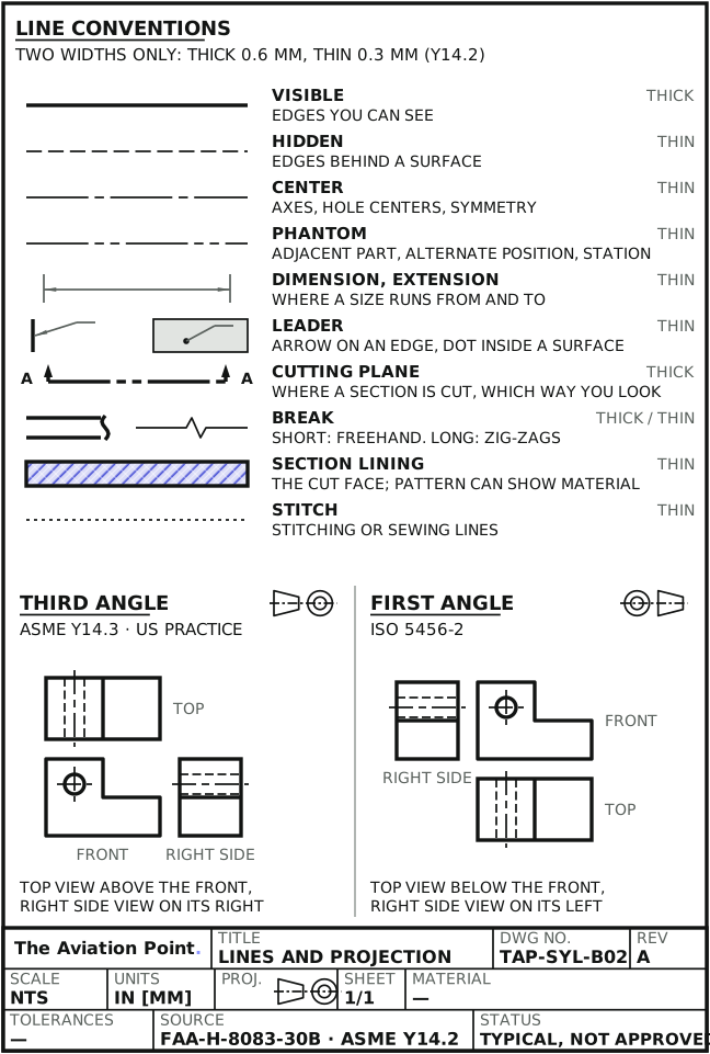
| Third-angle projection | US practice. Each view sits on the side it is seen from: top view above the front view, right-side view on its right. Symbol: the cone with its end view on the right | ASME Y14.3 |
| First-angle projection | Many European and ISO drawings. Each view sits opposite the side it is seen from: top view below, right-side view on the left. Symbol: the end view on the left | ISO 5456-2 |
| Section A-A | Cutting-plane line lettered A at both ends; the arrows point the way you look. The section is labeled SECTION A-A, with its scale | ASME Y14.3; FAA-H-8083-30B ch. 4, Lines and Their Meanings |
| Detail B | A circle round a feature, lettered B; the enlarged view is labeled DETAIL B with its scale | ASME Y14.3 |
| Aircraft views | Plan views of structure carry a FWD arrow, and the view label gives the direction of sight (LOOKING INBD, LOOKING FWD). Check both before you call a side left or right | TAP drawings; the maker's drawing standard governs its own |
| Pictorial views | Isometric, oblique and perspective: the part as the eye sees it; exploded views are pictorial too | FAA-H-8083-30B ch. 4, Methods of Illustration |
Lines and what they mean
| Line | Drawn as | Means | Source |
|---|---|---|---|
| Visible | Thick, continuous | Edges you can see | FAA-H-8083-30B ch. 4; ASME Y14.2 |
| Hidden | Thin, short dashes | Edges behind a surface | FAA-H-8083-30B ch. 4; ASME Y14.2 |
| Center | Thin, long and short dashes | Axes, hole centers, symmetry | FAA-H-8083-30B ch. 4; ASME Y14.2 |
| Phantom | Thin, a long dash and two short ones | Adjacent parts, alternate positions; on TAP drawings also station lines | FAA-H-8083-30B ch. 4; ASME Y14.2 |
| Dimension and extension | Thin, continuous; arrows on the dimension line | Where a size runs from and to | FAA-H-8083-30B ch. 4; ASME Y14.2 |
| Leader | Thin, continuous; an arrow on an edge, a dot inside a surface | Ties a note or callout to its feature | FAA-H-8083-30B ch. 4; ASME Y14.2 |
| Cutting plane | Thick, a long dash and two short ones, arrows at the ends | Where a section is cut and which way you look | FAA-H-8083-30B ch. 4; ASME Y14.2 |
| Break | Short: thick freehand. Long: thin with zig-zags | Part of a long piece left out | FAA-H-8083-30B ch. 4 |
| Section lining | Thin lines, usually at 45° | The cut face in a section; the pattern can show the material | FAA-H-8083-30B ch. 4 |
| Stitch | Very short dashes or dots | Stitching or sewing lines | FAA-H-8083-30B ch. 4 |
Two widths only. TAP figures use thick 0.60 mm and thin 0.30 mm, the minimums of ASME Y14.2.
Dimensions and tolerances, in [mm]
| Written | Read it as | Source |
|---|---|---|
| .250 | Decimal inch on a drawing: no zero before the point; the decimals show the precision | ASME Y14.5-2009 |
| .250 ±.005 | The dimension has the same number of decimals as its tolerance | ASME Y14.5-2009 |
| 0.8 (mm drawing) | Millimeters: zero before the point below 1 mm; whole millimeters without a point | ASME Y14.5-2009 |
| [6.35] | Millimeters in brackets under the inch value: reference only | TAP drawing note |
| 0.225 +0.0025 −0.0005 | Largest 0.2275, smallest 0.2245: tolerance 0.0030 in (0.076 mm) | FAA-H-8083-30B ch. 4, Tolerances |
| 0.225 ±0.0025 | 0.2225 to 0.2275: tolerance 0.0050 in (0.127 mm) | FAA-H-8083-30B ch. 4, Tolerances |
| 4X ⌀.1895–.1905 [4.814–4.838] | Four holes; limit dimensioning, low limit first on one line (or high limit over low). Here NAS618 column A for a -6 Hi-Lok pin | ASME Y14.5-2009; NAS618 |
| ⌀ R ⌵ ⌴ ↧ (.500) framed value | Diameter, radius, countersink, counterbore or spotface, depth, reference dimension, basic dimension | ASME Y14.5-2009 |
| 0.040 in (1.02 mm) | Running text and tables keep the zero before the point, so a faded point cannot turn .25 into 25 | TAP rule |
Millimeters: 1 in = 25.4 mm exactly, rounded to one decimal fewer than the inch value; limits rounded inward so they stay inside the inch limits (TAP rule).
Notes and flag notes
| Kind | How it is shown | Applies to | Source |
|---|---|---|---|
| General notes | Grouped together and numbered | The whole drawing | FAA-H-8083-30B ch. 4, Notes |
| Local note | Text with a leader to the feature | That feature | FAA-H-8083-30B ch. 4, Notes |
| Flag note | A number in a triangle at the feature; its text in the FLAG NOTES list | Only where the flag is | ASME Y14.100 |
| Quantity | 4X on the dimension; “(62) PL” or “TYP” on many aircraft callouts | Every identical feature | ASME Y14.5-2009 |
Fastener callouts and the rivet table
| On the drawing | What it says | Source |
|---|---|---|
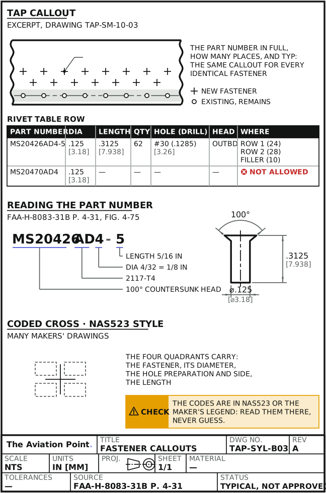
| MS20426AD4-5 | MS20426: 100° countersunk head. AD: 2117-T4. 4: diameter 4/32 = 1/8 in (3.18 mm). 5: length 5/16 in (7.938 mm) | FAA-H-8083-31B p. 4-31, Fig. 4-75 |
| “MS20426AD4-5 (62) PL, TYP” | Part number in full, the number of places, and the same callout for every identical fastener | TAP drawings |
| Rivet table | One line per part number: diameter, length, quantity, hole (drill), head side and where, in in [mm]. A part number that must not be used is listed as NOT ALLOWED | TAP drawings |
| + and ○ | + new fastener, its part number in full in the table; ○ existing fastener, remains | TAP drawings |
| Coded cross (NAS523 style) | Many makers' drawings put a cross at each fastener with codes in its quadrants: which fastener, its diameter, the hole preparation and side, the length. The codes are defined in NAS523 or in the maker's own legend: read them there, never guess a letter | NAS523; the maker's drawing legend |
TAP prints the full part number on every drawing, so nothing depends on a code table. Head codes, alloy letters and dash numbers: rivet identification. The same codes as a chart: rivet identification chart. Spacing and edge distance: rivet layout; what a repair drawing has to respect: repair principles.
Where on the aircraft: stations, zones, ATA chapters
Drawings place structure in the maker's coordinates, in inches from a datum: fuselage stations (FS or STA) from the reference datum, buttock lines (BL) left or right of the center line, water lines (WL) vertically, and wing, aileron, flap and nacelle stations on larger aircraft (FAA-H-8083-31B ch. 1, Location Numbering Systems, Figs. 1-88 to 1-91). Transport aircraft are also divided into zones and sub-zones whose digits are reserved (Fig. 1-92), and their manuals into ATA iSpec 2200 chapters: 51 to 57 for structure.
A station is a location, not a dimension: when a blueprint reads “fuselage frame station 137”, that frame is 137 in behind the zero station, the nose in the Handbook's example (FAA-H-8083-31B ch. 1). Each maker's system governs. The full tables and the record format: locating damage.
2Allowable damage
Before you work to it: when a drawing is not usable
| Check | Query or reject when | Source |
|---|---|---|
| Number and dash | The drawing or dash on the task is not the one on the part or in the SRM figure | FAA-H-8083-30B ch. 4, Reference and Dash Numbers |
| Revision | The print is not at the revision the task calls up: work to current data only | 14 CFR 43.13(a) |
| Approval | It is not approved data for this aircraft: the SRM, the maker's drawing or a repair design approved by the authority. A TAP drawing is typical, not approved data | Reg. (EU) 748/2012 Part 21 Subpart M; 14 CFR 43.13 |
| Scale | A size is needed that is not written: never measure the print, prints are enlarged and reduced. Ask for the dimension | FAA-H-8083-30B ch. 4, Scale |
| Legibility | A copy from film, fax or scan where a decimal point, a minus sign or a digit is in doubt | TAP rule: query, never guess |
A wrong revision or a wrong dash is a wrong part: it is found by reading, not by fitting.
3Repair
Reading a drawing, step by step
| Step | Action | What to do |
|---|---|---|
| 1 | Title block | Drawing number, dash, title, sheet n of N, scale, units line, projection symbol, general tolerances, material. |
| 2 | Revision | The latest entry in the revision block: symbol, date, what changed. Compare it with the revision the task calls up. |
| 3 | Orientation | The main view, the direction of sight (LOOKING INBD) and the FWD arrow. Find each section and detail by its letters. |
| 4 | Location | Stations, stringers, frames and zones that place the work on the aircraft. |
| 5 | Dimensions | From which datum or edge each size runs, and its tolerance or the general one. The inch value is the size; [mm] is the reference. |
| 6 | Notes | General notes apply everywhere; a flag note only where its flag is. |
| 7 | Parts and fasteners | Balloons to the parts list, crosses to the rivet table: part numbers, quantities, new or existing. |
| 8 | Before the first hole | Counts, edge distances and pitches against the SRM. Query anything that does not add up. |
Worked example: reading drawing TAP-SM-10-03
TAP training drawing TAP-SM-10-03, rev A: a flush patch on a fuselage skin. Plan view looking inboard, scale 1:2, FWD arrow to the left; section A-A and detail B at 2:1; frames FR 14 at STA 284.00 and FR 15 at STA 294.00; stringers STGR 12 and 13; the patch center line dimensioned 4.00 in from FR 14; leader callout “MS20426AD4-5 (62) PL, TYP”; a rivet table; parts list items 1 to 4; three flag notes.
- Title block: TAP-SM-10-03, rev A, sheet 1/1, units IN [MM], third-angle symbol, status TYPICAL, NOT APPROVED. A training drawing: the SRM governs any real repair.
- Frame pitch: 294.00 − 284.00 = 10.00 in (254.0 mm). Patch center: 284.00 + 4.00 = STA 288.00.
- Looking inboard with FWD to the left puts you on the left side of the aircraft: a left-hand skin.
- Callout: MS20426 (100° countersunk), AD (2117-T4), 4 = 1/8 in diameter, 5 = 5/16 in long, 62 places. The rivet table gives the hole, #30 (0.1285 in, 3.26 mm), and splits the 62: row 1 24, row 2 28, filler 10.
- MS20470AD4 is in the table as NOT ALLOWED: a protruding head on a skin that must stay flush.
- Flag notes apply only where their flags are: 1 trim the opening and fit the filler, 2 dimple the three parts, 3 doubler one gauge heavier than the skin.
- Parts list: 1 skin, existing, 2024-T3 clad 0.040 in (1.02 mm); 2 filler, new; 3 doubler, new, 0.050 in (1.27 mm); 4 rivets, 62.
Patch centered at STA 288.00 between STGR 12 and 13, on a left-hand skin; 62 MS20426AD4-5 rivets in #30 holes; no protruding heads. Every value came from the drawing itself: nothing was scaled.
Drawing changes, formats and records
| Item | What to know | Source |
|---|---|---|
| Revision | A change gets a new revision symbol and a line in the revision block, with date and description; the earlier print is superseded | FAA-H-8083-30B ch. 4, Revision Block |
| Who changes it | The design holder: the type-certificate holder, or the organization approved for that repair design. In the hangar a deviation is queried, not drawn in | Reg. (EU) 748/2012 Part 21 Subpart M; 14 CFR 43.13 |
| Microfilm and microfiche | Older drawings and manuals kept on film and read in a viewer: check that the frame is complete and legible | FAA-H-8083-30B ch. 4; Part-66 7.5 |
| Digital | PDF, CAD models, electronic manuals: the same rules; the revision on the screen must be the current one | FAA-H-8083-30B ch. 4; Part-66 7.5 |
| Standards on the drawing | MS (Military Standard), NAS (National Aerospace Standard), AN (Army/Navy), MIL specifications and standards, ISO: the prefix tells you who owns the standard behind the part number | FAA-H-8083-31B p. 4-31; Part-66 7.5 |
| ATA chapters | Manuals are split by ATA iSpec 2200 chapter; structure is 51 to 57 | ATA iSpec 2200 |
| Record | The drawing number and revision you worked to go in the record of the work | 14 CFR 43.9(a)(1) |
Quick check
A dimension reads 0.225 +0.0025 −0.0005. What is the largest acceptable size?
- 0.2275 in
Best fit. Yes: 0.225 + 0.0025 (FAA-H-8083-30B ch. 4, Tolerances).
- 0.2245 in
Not this one. That is the smallest: 0.225 − 0.0005.
- 0.2280 in
Not this one. That adds the whole tolerance, 0.0030 in, to the nominal size.
On a real job, the SRM decides.
Questions people actually ask
Is an aircraft drawing in first or third angle?
Drawings to ASME practice use third angle (ASME Y14.3); many European and ISO drawings use first angle (ISO 5456-2). The symbol in the title block settles it: read it before you name a view.
Why does the drawing write .250 and your tables 0.250?
On an inch drawing ASME Y14.5 leaves out the zero before the point, and the decimals show the precision. In text and tables we keep the zero, so a faded point cannot turn .25 into 25.
Can I measure the print if a dimension is missing?
No. Prints are enlarged and reduced when they are copied, printed or shown on a screen. Ask for the dimension (FAA-H-8083-30B ch. 4, Scale).
What does a dash number mean?
A variant of the part on the same drawing, often -1 left hand drawn and -2 right hand opposite. The parts list says what changes between them.
What is a NAS523 rivet code?
A coded cross at each fastener, used on many makers' drawings. The codes are in NAS523 or in the maker's legend; without that legend the code cannot be read. TAP drawings print the full part number instead.
Where are stations measured from?
From the maker's datum, in inches: FS from the reference datum, BL from the center line, WL vertically. See locating damage.
Limits of this guide
What the sources support, and no further.
- The maker's drawing standard governs its own drawings: symbols, codes and abbreviations differ between makers.
- NAS523 codes are not reproduced: read them from the standard or the legend that comes with the drawing.
- ASME and ISO standards are named for their conventions; the edition the drawing calls up governs.
- TAP drawings are typical, not approved data: the SRM, the maker's drawing or an approved repair design governs a real repair.
- Wiring diagrams and schematics are named in Part-66 7.5; this page reads the structural drawing.
Where to buy
Are you a distributor? Get listed →
Distributors coming soon.
Keep going
Calculators
Guides
How to do it
Books
Main sources
- FAA-H-8083-30B, Aviation Maintenance Technician Handbook: General (2023) — Ch. 4, Aircraft Drawings: types of drawings, sectional views, title blocks, drawing, reference and dash numbers, bill of material, revision block, notes, tolerances, finish marks, scale, lines and their meanings, orthographic projection, methods of illustration, microfilm and digital images.
- FAA-H-8083-31B, Aviation Maintenance Technician Handbook: Airframe — Ch. 1, Location Numbering Systems, Figs. 1-88 to 1-92; p. 4-31 and Fig. 4-75, rivet identification and the MS, NAS and AN systems.
- ASME Y14.5-2009, Dimensioning and Tolerancing — Millimeter and decimal-inch dimensions, repetitive features, limit dimensioning and symbols: named as what governs, not reproduced.
- ASME Y14.2, Line Conventions and Lettering — Line types and line widths: named as what governs, not reproduced.
- ASME Y14.3, Orthographic and Pictorial Views — Third-angle projection, sections and details.
- ISO 5456-2, Technical drawings: Projection methods, Part 2: Orthographic representations — First- and third-angle projection and their symbols.
- ASME Y14.100, Engineering Drawing Practices — Notes and flag notes.
- NAS523 — Fastener symbols and codes on drawings: named, not reproduced.
- NAS618 — Column A hole for the -6 pin, as listed in the Hi-Lok holes guide.
- ATA iSpec 2200 — Chapter numbering of the manuals; 51 to 57, structure.
- 14 CFR 43.9 and 43.13 — 43.9(a)(1), reference to the data used, in the record; 43.13(a), current manufacturer's data.
- Regulation (EU) No 748/2012, Annex I (Part 21), Subpart M — Repairs: who approves a repair design.
- Regulation (EU) No 1321/2014, Annex III (Part-66), Appendix I, as amended by Regulation (EU) 2023/989 — Module 7.5, syllabus wording.
- FAA-S-ACS-1, Aviation Mechanic General, Airframe, and Powerplant Airman Certification Standards — AM.I.B Aircraft Drawings.
Cross-checked with other manuals and standards in our library.