1Identification
Where to buyThe drawing
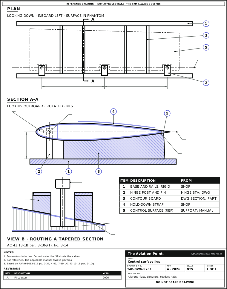
Fixtures and what each one does
| Fixture | What it does | Who makes it | Source |
|---|---|---|---|
| Cradle | Holds a control surface, wing panel or stabilizer while it is off the aircraft; the aircraft stays on its gear or on jacks | Prepared by the shop for the component | FAA-H-8083-31B p. 4-91 |
| Repair jig | Holds parts in position to keep their shape and distributes the loads while an extensive repair is made | Constructed for the repair; support requirements from the maintenance manual | p. 4-91, fig. 4-171 |
| Balancing stand, jig or fixture | Carries the removed surface on its own hinge points, free to rotate, with the chord line level for neutral | Locally fabricated (fig. 2-61); the balance-beam tool to the manufacturer's instructions and dimensions | pp. 2-37, 2-38 |
| Rigging fixture, contour template | Measures control surface travel; markings on it show the travel wanted | Designed by the manufacturer | p. 2-43 |
| Support tooling, mold | Supports a bonded or composite part and keeps its contour during cure; in an oven or autoclave the part deforms without it | Plaster for a temporary tool; tooling resin with fiberglass or carbon for a permanent one; metal or tooling board for masters | p. 7-19; TO 1-1A-1 par. 7.2.2.5 |
| Routing template with wedge block | On a tapered section such as an aileron, lets the router cut the core parallel with the lower surface | Shop made | AC 43.13-1B par. 3-10g(1), fig. 3-14 |
| Welding jig or fixture | Holds the elements to be welded rigidly enough to prevent misalignment from expansion and contraction, and positions them accurately | Shop made | AC 43.13-1B par. 4-77a |
What governs the fixture
| Feature | Why it governs | Where the value comes from | Source |
|---|---|---|---|
| Hinge line | The surface is supported from its own points and must rotate freely about them; friction gives a false balance reaction | Hinge stations and fittings: aircraft drawing and maintenance manual | FAA-H-8083-31B p. 2-37, fig. 2-61 |
| Neutral, chord line | Neutral is set with the chord line horizontal, checked with a bubble protractor | Where the protractor sits: the maintenance manual | p. 2-37, fig. 2-62 |
| Contour | The jig keeps the shape while parts are out; cure tooling keeps the surface contour | Drawing sections at the rib stations, or a tool molded to the part | pp. 4-91, 7-19 |
| Twist | Pins on one hinge line and boards at their stations hold the surface as it was built; the repair keeps what the fixture holds | —: the aircraft SRM or maintenance manual sets the tolerance | AC 43.13-1B par. 1-38 (structure identical to the original) |
| Balance after repair | Weight added aft of the hinge line can induce flutter; balance stays within the original or maximum allowable value | Balance limits and weights: the manufacturer's instructions | AC 43.13-1B pars. 1-38 (wood), 2-5f (fabric), 4-36a (metal); TO 1-1A-1 par. 1.7.1 |
| Flaps with no fixed hinge line | Fowler flaps move rearward on their drives instead of turning on a stationary hinge line, so the fixture takes the flap's own support fittings | Support points: the maintenance manual | TO 1-1A-1 par. 1.7.2.2.3; FAA-H-8083-31B p. 2-37 |
2Allowable damage
When a fixture is needed
| Work | What holds it | Source |
|---|---|---|
| Any surface taken off for repair | A cradle; the aircraft on its gear or jacks, and the adjacent structure supported where it carries static loads | FAA-H-8083-31B p. 4-91 |
| Extensive repair | A jig that holds the parts in position and keeps their shape. The handbook's examples are the fuselage, landing gear and wing center section; the manual says when a surface needs one | p. 4-91 |
| Rebalancing by the scale or balance-beam method | Surface off the aircraft on a support stand and balancing jigs; the calculation method can be done on the aircraft | pp. 2-37, 2-38 |
| Bonded or composite repair cured in an oven or autoclave | Support tooling; without it the part deforms | p. 7-19; TO 1-1A-1 par. 7.2.2.5 |
| Core removal in a tapered section | Routing template with a wedge block | AC 43.13-1B par. 3-10g(1) |
| Welding a surface frame | A rigid welding jig or fixture | AC 43.13-1B par. 4-77a |
| Rigging and travel after refit | The manufacturer's rigging fixtures and contour templates | FAA-H-8083-31B p. 2-43 |
The limits the fixture has to protect
| Check | Limit | Source |
|---|---|---|
| Rotation on the hinge points | Free, without binding; excessive friction gives a false over- or underbalance | FAA-H-8083-31B p. 2-37 |
| Neutral | Chord line horizontal, checked with a bubble protractor | p. 2-37, fig. 2-62 |
| Balance | Within the specified tolerances, and within the original or maximum allowable value. The values: —, the manufacturer's manual | p. 2-37; AC 43.13-1B par. 4-36a |
| Arm, calculation method | Hinge center line to the center of the repair, to the nearest 0.01 in [0.25 mm] | p. 2-37 |
| Scale, scale method | Graduated in hundredths of a pound: 0.01 lb [4.5 g] | p. 2-38 |
| Tab free play, tab span not over 35 % of the surface span | Total at the tab trailing edge not over 2 % of the tab chord | AC 43.13-1B par. 4-36d(1) |
| Tab free play, tab span 35 % or more | Not over 1 % of the distance from the tab hinge line to the trailing edge, perpendicular to the hinge line | par. 4-36d(1) |
| Paint | No coats beyond what the manufacturer applied | par. 4-36b |
| Drainage and ventilation | Kept as built: water or ice trapped in a surface has caused flutter | par. 4-36c |
| Hinge-line straightness, contour and twist | —: the aircraft SRM or maintenance manual | No public generic value |
3Repair
Making and using a holding fixture
| Step | Action | What to do |
|---|---|---|
| 1 | Get the data | The maintenance manual's support points, the SRM repair and any tool the manual names. Tools and equipment in the maintenance instructions are to be available and used (AC 43.13-1B par. 5-2, on 14 CFR part 43): ask your quality system before you use a local copy. |
| 2 | Lay it out from the drawing | Hinge stations and the hinge center line, the rib stations and the section contour at each one (reading aircraft drawings, sheet layout). |
| 3 | Pick up the hinge fittings | Pins in the surface's own fittings, all on one hinge center line, posts on a rigid base: the surface hangs from its own points, as in the locally made fixture of FAA-H-8083-31B fig. 2-61. |
| 4 | Add the contour | Boards at the rib stations cut to the drawing section, or a tool molded to the part. Plaster for a temporary tool, tooling resin with fiberglass or carbon for a permanent one; the material suits the cure temperature (p. 7-19). |
| 5 | Check the fixture first | Pin line, stations and contours against the drawing, with calibrated measuring tools (calibration), before the part goes in. |
| 6 | Support, remove, mount | Aircraft on its gear or jacks, adjacent structure supported where it carries static loads (p. 4-91). On the stand, trim tabs secured in neutral and other assemblies on or off as the manual says (p. 2-37). |
| 7 | Repair in the fixture | Keep the structure identical to the original, with stiffness, weight distribution and mass balance unaffected (AC 43.13-1B par. 1-38). Cut core in a tapered section with the wedge block under the template (par. 3-10g(1)). |
| 8 | Check the balance | Level stand, no air currents, chord line level, the manufacturer's method and limits (control surface rebalancing). After balance weights are added or removed, AC 43.13-1B par. 4-36a calls for flight testing to make sure flutter is not a problem. |
| 9 | Refit, rig and record | Travel with the manufacturer's rigging fixtures or templates (p. 2-43; control surface alignment). Record the repair, the weights and the fixture used. |
Checks in the fixture
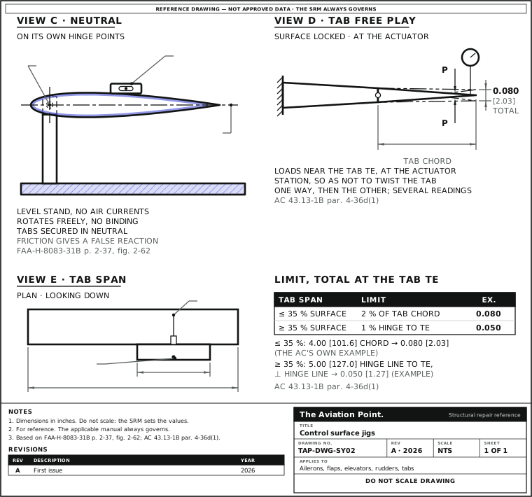
Worked example: tab free play after a tab repair
A trim tab was repaired with the elevator held in its fixture. The tab chord is the AC's own example; the reading is drawn for the format, and the aircraft manual's values come first when it gives them.
- Lock the elevator so it cannot move. Apply a point load up, then down, near the tab trailing edge at the span-wise station of the actuator, so as not to twist the tab, and read a dial gauge near the trailing edge; take several readings each way (AC 43.13-1B par. 4-36d(1)).
- The tab span does not exceed 35 % of the elevator span, so the limit is 2 % of the tab chord.
- Tab chord 4.00 in [101.6 mm]: 4.00 × 0.020 = 0.080 in [2.03 mm], total motion up and down at the trailing edge.
- Reading: 0.065 in [1.65 mm] total. Within the limit; over 0.080 in, the free play is corrected before the surface goes back.
Limit 0.080 in [2.03 mm] total; 0.065 in [1.65 mm] is within. Only a minor amount of tab-mechanism wear can be tolerated (par. 4-36d).
Quick check
A repaired aileron hangs on its hinge points in the balancing fixture, but one hinge pin binds. What happens to the balance check?
- Nothing: the trailing edge still shows the balance
Not this one. No: the balance is read from the trailing edge, and excessive friction gives a false reaction (FAA-H-8083-31B p. 2-37).
- It cannot be trusted: free the hinge points first
Best fit. Yes: the surface must rotate freely about its hinge points without binding, or the over- or underbalance it shows is false (p. 2-37).
- It reads underbalanced, so add weight forward
Not this one. No: friction can hide either condition, and weights go on only as the manufacturer instructs (AC 43.13-1B par. 4-36a).
On a real job, the SRM decides.
Questions people actually ask
Can I make my own jig or fixture?
Where the manual allows it. The handbook shows a locally fabricated balancing fixture (FAA-H-8083-31B fig. 2-61) and says the balance-beam tool is made locally to the manufacturer's instructions and dimensions (p. 2-38). Tools named in the maintenance instructions are to be available and used (AC 43.13-1B par. 5-2): ask your quality system before you use a local copy.
Where do the hinge stations and contours come from?
From the aircraft drawing and the maintenance manual: hinge stations, rib stations, sections and support points. For a bonded or composite repair the support tool can be molded to the part's own contour (FAA-H-8083-31B p. 7-19).
Is there a public twist or hinge-line tolerance?
No. The public documents give the method, not the numbers: twist, contour and hinge-alignment tolerances are the aircraft SRM's or maintenance manual's.
Does the surface have to come off to be rebalanced?
Not for the calculation method, which can be done on the aircraft. The scale and balance-beam methods need it off, on a stand with balancing jigs (FAA-H-8083-31B pp. 2-37, 2-38).
Does a trailing-edge repair need a fixture?
The SRM decides. Trailing edges are not structural members but are considered highly stressed in all cases (FAA-H-8083-31B p. 4-106), and any repair aft of the hinge line moves the balance (AC 43.13-1B par. 1-38).
What about Fowler flaps?
They have no stationary hinge line: they move rearward on their drives (TO 1-1A-1 par. 1.7.2.2.3). The fixture takes the flap's own support fittings, as the maintenance manual shows.
Limits of this guide
What the sources support, and no further.
- The aircraft manual governs. Support points, hinge stations, contours and any special tool are the maintenance manual's and SRM's.
- No fixture dimensions. The public documents show the idea of a cradle, a jig and a balancing fixture, not their sizes or materials.
- No twist, contour or hinge-line tolerances: none is published as a general figure.
- Tab free play values are those of AC 43.13-1B par. 4-36d(1); the aircraft manual's own values come first.
- Rotor blades and rotor controls follow their own tooling and are not covered here.
- mm values are conversions for reference; inches govern.
Where to buy
Are you a distributor? Get listed →
Distributors coming soon.
Keep going
Calculators
Guides
How to do it
Books
Buy
Distributors coming soon.
Main sources
- FAA-H-8083-31B, Aviation Maintenance Technician Handbook — Airframe (2023) — Ch. 2: p. 2-16 (rigging: pins, clamps or jigs), pp. 2-37 and 2-38 (rebalancing procedures and methods; figs. 2-61 and 2-62), p. 2-43 (rigging fixtures and contour templates). Ch. 4: p. 4-91 (structural support during repair; fig. 4-171), p. 4-106 (trailing edges). Ch. 7: p. 7-19 (caul plate, support tooling and molds).
- FAA AC 43.13-1B, Acceptable Methods, Techniques, and Practices — Aircraft Inspection and Repair — Par. 3 (14 CFR 43.13(a)); par. 1-38 (control surface flutter precautions); par. 2-5f (flutter precautions, fabric); par. 3-10g(1) and fig. 3-14 (routing a tapered control surface); par. 4-36a to d (flutter and vibration precautions, tab free play); par. 4-77a (welding jig or fixture); par. 5-2 (tools in the maintenance instructions).
- TO 1-1A-1 / NAVAIR 01-1A-1, General Manual for Structural Repair — Par. 1.7.1 (WARNING on static balance) and 1.7.1.4 (balance weights forward of the hinge line); par. 1.7.2.1 (main control surface structure); par. 1.7.2.2.3 (flaps, Fowler flaps); par. 7.2.2.5 (holding fixtures for adhesive bonding).
Cross-checked with other manuals and standards in our library.