1Identification
Where to buyThe drawing
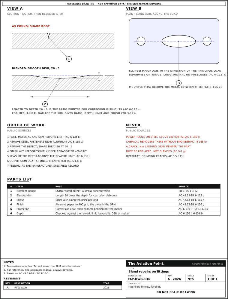
What you are blending and why
| Item | What the sources say | Source |
|---|---|---|
| Stress concentration | A fatigue crack starts more readily where the design or the surface gives a stress concentration: fillets, sharp radii, a poor surface finish, seams, grinding cracks | AC 43.13-1B par. 5-5 e (3); TO 1-1A-1 par. 2.5.2.1 |
| Why a notch is blended | Blending a scratch on load-bearing structure reduces the stress concentration; the SRM gives the blend allowance and the acceptable finish | TO 1-1A-1 par. 3.12 and fig. 3-12 |
| Notch-sensitive alloy | 7075-T6 is more notch sensitive than 2014 and 2024: avoid notches, small radii, machine marks, nicks, dents, burrs and scratches | AC 43.13-1B par. 4-58 b |
| Tool marks and corners | Parts are left free from cracks, tool marks, rough edges and notches caused by cutting or grinding; corners and holes take generous radii | TO 1-1A-1 par. 3.1.1 |
| Flaws already in the part | Forging laps and bursts, machining tears, heat-treat cracks at fillets and notches, grinding cracks: found by inspection, not by blending | AC 43.13-1B par. 5-5; TO 1-1A-1 pars. 2.5.2.2, 2.5.2.3 |
| Material and heat treatment | From the drawing or the SRM. Steel heat-treated above Rockwell C40 (180 000 psi) changes how metal may be removed | AC 43.13-1B par. 6-165 |
Defects that a blend can remove: scratch, nick, gouge, cut, burr and corrosion pit; definitions in the damage classification guide.
2Allowable damage
What the public documents set
| Item | Published rule | Source |
|---|---|---|
| Ratio, corrosion dish-outs | 20 : 1, length to depth, smoothly blended; elliptical, major axis spanwise on wings and horizontal stabilizers, longitudinal on fuselages, vertical on vertical stabilizers | AC 43.13-1B par. 6-115 a, c |
| Ratio and depth, mechanical damage | —: the aircraft SRM gives the blend allowance. 20 : 1 is not a general rule for a scratch or nick | TO 1-1A-1 par. 3.12 |
| Rework depth limit | —: the SRM. Determine the depth of the faired depression to be sure the limit is not exceeded; beyond it the aircraft manufacturer or a DER decides | AC 43.13-1B pars. 6-136 i, 6-134 b |
| Which pits to blend | Critical and highly stressed areas: every pit left after removing the corrosion. Non-critical structure: pits left by blasting need not be blended out, which would only take more metal | AC 43.13-1B par. 6-115 b |
| Surface finish | Abrasive paper progressively finer to 400 grit (aluminum); magnesium and steel: 240, then 300, then 400 grit. A roughness value is —: the SRM | AC 43.13-1B pars. 6-136 g, 6-152 h, 6-167 h; TO 1-1A-1 par. 3.12 |
| Fillet radius | —: the drawing or the SRM. Sharp corners are avoided and radii at holes and edges are generous | TO 1-1A-1 par. 3.1.1 |
| Cracks | A crack in a landing-gear member: the part is replaced. No crack is negligible until the damage limits are known; beyond repair boundaries it goes to engineering | AC 43.13-1B par. 9-4 g; TO 1-1A-1 Table 2-1, par. 3.11.3.6 |
| Small nicks and cuts | On a landing-gear member they can be filed and burnished to a smooth contour, removing the stress concentration | AC 43.13-1B par. 9-4 g |
| Heat | Heavy continuous abrasive grinding can heat the metal enough to change it: if suspected, hardness or conductivity tests. Grinding cracks run at right angles to the grinding direction, shallow and sharp at the root | AC 43.13-1B pars. 6-136, 5-5 d (3) |
| High-strength steel | Heat-treated above Rockwell C40, 180 000 psi: mild abrasive mats, cloths and papers; a power tool is undesirable (overheating, notches); chemical removers are prohibited without engineering authorization (hydrogen embrittlement) | AC 43.13-1B par. 6-165 |
| Shot peening | Peening is a way of producing compressive residual stress in a part; the sources print no intensity, coverage or media: —, the manufacturer's drawing or manual | AC 43.13-1B par. 6-39; TO 1-1A-1 app. C par. C.11 |
Every cell stops where the document stops. A cell showing — is a value the SRM or the drawing gives.
3Repair
Step by step
| Step | Action | What to do |
|---|---|---|
| 1 | Get the limit first | Part, material and the rework limit from the SRM or the drawing. Beyond the SRM limit, the manufacturer or a DER (AC 43.13-1B par. 6-134 b). A crack in a landing-gear member means a new part (par. 9-4 g). |
| 2 | Inspect before you remove metal | Clean and look at the defect and its surroundings with a magnifier; NDI as the SRM requires. Grinding cracks and tool marks show up here (AC par. 5-5; TO 1-1A-1 par. 2.5.2). |
| 3 | Take steel hardware away from aluminum | Remove steel nut-plates and steel fasteners before blending aluminum: steel or copper particles embedded in it start new corrosion (AC par. 6-115 c). |
| 4 | Remove the defect, shape the dish | Elliptical, long axis along the principal load, length 20 times the depth where the rule is 20 : 1, or the ratio the SRM names. No power tool on steel above 180 000 psi (par. 6-165). |
| 5 | Finish with finer abrasive | Progressively finer abrasive paper up to 400 grit, or the finish the SRM states. Keep heat out of the part (par. 6-136). |
| 6 | Measure the depth after finishing | Against the rework limit. The ratio is for the dish you end up with: if the depth grew during finishing, check the length again (par. 6-136 i). |
| 7 | Protect it at once | Chemical conversion coat immediately after reworking, then primer and finish. Re-apply the conversion coat if 48 hours pass without primer (par. 6-136 j, k; TO 1-1A-1 par. 3.11.3.5). |
| 8 | Restore the peening and record it | Where the area was peened, the manufacturer gives the peening to restore. Record place, depth, length, ratio, finish, inspection and the SRM reference (14 CFR 43.9). |
Blending: the ratio and who sets it
| Point | What each document says | Agree or differ |
|---|---|---|
| Blend ratio | AC 43.13-1B pars. 6-115 and 6-136 g: smooth blended dish-outs at 20:1, length to depth (Fig. 6-15). T.O. 1-1A-1 par. 3.12 and Fig. 3-12: blend scratches on load-bearing structure to cut the stress concentration; the allowance and the finish come from the weapon system's structural repair manual. | The AC gives the ratio; the T.O. gives none and sends you to the SRM. Use the SRM's allowance, and 20:1 where it is silent. |
AC 43.13-1B CHG 1 pars. 6-115 and 6-136 g and Fig. 6-15; T.O. 1-1A-1 par. 3.12.
Protection after the blend
| Step | Rule | Source |
|---|---|---|
| Conversion coat | MIL-C-81706 immediately after reworking; if 48 hours or more pass and no primer or paint has gone on, apply it again before going on | AC 43.13-1B par. 6-136 j |
| Primer | Epoxy primer MIL-P-23377 to a minimum dry-film thickness of 0.0012 in (US military repair practice); a manufacturer's system overrides it | TO 1-1A-1 par. 3.11.3.5 |
| Where not to use the solutions | Not on magnesium or on steel of 180 000 psi and above: they must not contact those metals; no paint thinner, acetone or other combustible material near them | AC 43.13-1B par. 6-136 j (note) |
| Shot peening | —: intensity, coverage and media from the manufacturer's drawing or manual | AC 43.13-1B par. 6-39 |
| Health and safety | Alodine and epoxy primer are toxic: eye and skin protection, good general ventilation | TO 1-1A-1 par. 3.11.3 (warning) |
Worked example: three blends at 20 : 1
| Case | Arithmetic | Result |
|---|---|---|
| Scratch 0.012 in deep on a 7075-T6 forged fitting, corrosion rule applied | 20 × 0.012 = 0.240 in long | Dish 0.240 in long, 0.012 in deep, long axis along the load; SRM limit: — |
| Pit 0.030 in deep, critical area | 20 × 0.030 = 0.600 in | 0.600 in of dish; all pits left after removal blended out (AC 6-115 b) |
| Same scratch, depth 0.012 in measured before finishing and 0.018 in after | 20 × 0.018 = 0.360 in against 0.240 in blended | The dish is too short: lengthen it to 0.360 in, then measure again |
| Depth after finishing 0.018 in, SRM rework limit — | The limit is the SRM's | Inside: finish, coat, record. Beyond: manufacturer or DER (AC 6-134 b) |
Arithmetic of the 20 : 1 rule on example sizes. The 20 : 1 ratio is printed for corrosion dish-outs; for a mechanical defect the SRM ratio applies.
What to check when it is done
| Look at | Good | Source |
|---|---|---|
| Defect | Gone: no trace under magnification or the NDI the SRM calls for | AC 43.13-1B par. 6-136 g; TO 1-1A-1 par. 3.11.3.4 |
| Shape | Smooth elliptical dish, no sharp root, no tool marks or ridges, long axis along the load | AC par. 6-115 a; TO par. 3.1.1 |
| Depth | Inside the rework limit of the SRM | AC par. 6-136 i |
| Finish | Final abrasive pass done, no heat discoloration | AC par. 6-136 g |
| Protection | Conversion coat and primer on, no bare metal | AC par. 6-136 j |
| Record | Position, size, ratio, finish, inspection, SRM reference | 14 CFR 43.9 |
Quick check
A 0.020 in deep pit is blended at 20 : 1. How long is the dish?
- 0.400 in
Best fit. Yes: 20 × 0.020 = 0.400 in, along the load direction.
- 0.040 in
Not this one. No: that is twice the depth.
- 0.100 in
Not this one. No: that is five times the depth.
On a real job, the SRM decides.
Questions people actually ask
Is 20 : 1 the ratio for any blend?
It is the ratio printed for corrosion dish-outs (AC 43.13-1B par. 6-115 c). For a mechanical defect on a fitting the SRM gives ratio and depth limit (TO 1-1A-1 par. 3.12).
How deep may I go?
The public documents give no depth. The SRM sets the rework limit per part; beyond it the manufacturer or a DER decides.
Can I blend out a crack?
Not on a landing-gear member: the part is replaced (AC 43.13-1B par. 9-4 g). Elsewhere a crack is not negligible until its limits are known (TO 1-1A-1 Table 2-1).
Do I have to shot peen again?
If the area was peened, the manufacturer's drawing or manual gives the peening to restore. The sources used here print no intensity or coverage.
Limits of this guide
What the sources support, and no further.
- The SRM or the drawing governs. Blend ratio, depth limit, roughness and fillet radius for a part are theirs; none is printed in the documents used here.
- 20 : 1 is the corrosion ratio of AC 43.13-1B, not a rule for every defect.
- No peening data (intensity, coverage, media) is published here.
- No roughness value is given: the finish is stated by grit sequence only.
- Typical, not authority. Methods are examples; the SRM governs.
Where to buy
Are you a distributor? Get listed →
Distributors coming soon.
Keep going
Calculators
Guides
How to do it
Books
Buy
Distributors coming soon.
Main sources
- AC 43.13-1B with Change 1, Acceptable Methods, Techniques, and Practices — Par. 4-58 b (7075-T6); par. 5-5 (flaws); par. 6-39 (shot peening); pars. 6-115, 6-134, 6-136 (blending, rework, examples); par. 6-152 h (magnesium); par. 6-165 and 6-167 (steel); par. 9-4 g (landing gear).
- TO 1-1A-1 / NAVAIR 01-1A-1, General Manual for Structural Repair (15 Jan 2016) — Pars. 2.5.2.1 to 2.5.2.3 (stress concentration, cracks from heat treat and grinding); par. 3.1.1 (corners, tool marks); pars. 3.11.3.4 to 3.11.3.6 (crack repair, protection); par. 3.12 and fig. 3-12 (blending scratches); app. C par. C.11.
- 14 CFR Part 43, par. 43.9 — Maintenance record content.
Cross-checked with other manuals and standards in our library.