1Identification
Where to buyThe drawing
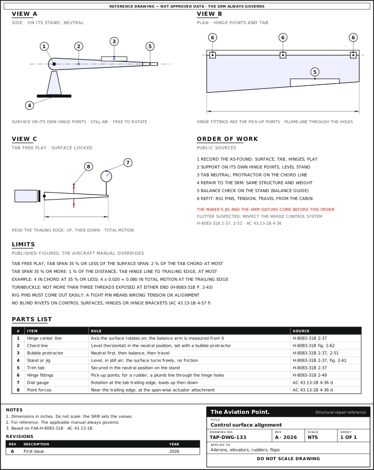
Datums and pick-up points
| Datum | What it is and how it is used | Source |
|---|---|---|
| Hinge center line | The axis the surface turns on. The balance arm of a repair is measured from it, to the nearest 0.01 in | FAA-H-8083-31B p. 2-37 |
| Own support points | A surface to be rebalanced is removed and supported from its own points on a stand, jig or fixture; a locally made fixture holds it at the inboard and outboard hinge fittings | FAA-H-8083-31B p. 2-37, fig. 2-61 |
| Chord line, neutral | The neutral position is set with the chord line horizontal, checked with a bubble protractor, before any balancing | FAA-H-8083-31B p. 2-37, fig. 2-62 |
| Trim tab | Secured in the neutral position on the stand. When rigging, the tab is usually set to streamline; some aircraft call for an offset of a degree or two | FAA-H-8083-31B pp. 2-37, 2-52 |
| Rudder hinge holes | With the rudder off, a plumb line passed through the hinge attachment holes should run centrally through all of them. Some fins have the leading edge offset from the longitudinal center line on purpose | FAA-H-8083-31B p. 2-49 |
| Fin lateral datum | Fin verticality: measure from a given point on each side of the fin top to a given point on the left and right stabilizers; the two should agree within the prescribed limits | FAA-H-8083-31B p. 2-49, fig. 2-86 |
| Rig pins | A small pin or clip that sets pulleys, levers and bellcranks in neutral. Without pins, neutral is set by alignment marks, templates or linear measurement | FAA-H-8083-31B p. 2-52 |
| Rigging fixtures and templates | Gauges made by the manufacturer; their markings show the surface travel wanted | FAA-H-8083-31B pp. 2-43, 2-51 |
Tolerances, datum positions and the maker's jig are in the aircraft maintenance manual; none is printed in the public documents.
Holding and measuring tools
| Tool | What it does | Source |
|---|---|---|
| Stand, jig or fixture | Holds a removed surface on its own hinge points; level, in an area free of air currents. A jig holds a part in shape while it is repaired. Cradles are made for parts taken off the aircraft | FAA-H-8083-31B pp. 2-37, 4-91 |
| Bubble protractor | Establishes the neutral position, then reads the chord line level while balancing | FAA-H-8083-31B p. 2-37 |
| Universal propeller protractor | Frame, disc, ring and two spirit levels; measures aileron, elevator or flap travel. The disc and ring turn independently; a double 10-part vernier is on the ring | FAA-H-8083-31B pp. 2-51, 2-52, fig. 2-90 |
| Rigging fixture, contour template, rule | Travel is measured in degrees, or in inches with a rule when the maker gives inches | FAA-H-8083-31B pp. 2-43, 2-51 |
| Dial gauge | Rotation at the tab trailing edge for the free-play check | AC 43.13-1B par. 4-36 d |
| Tensiometer | Cable tension from the force to offset the cable between two hardened anvils; a riser per cable size and a conversion chart from dial reading to pounds. 98 percent accurate when maintained, and calibrated | FAA-H-8083-31B pp. 2-43, 2-50 |
| Plumb bob, spirit level, incidence and dihedral boards | Alignment of the structure the surface hangs on: dihedral, incidence, fin verticality, symmetry | FAA-H-8083-31B pp. 2-47 to 2-49 |
2Allowable damage
What a control surface repair must not change
| Condition | Rule | Source |
|---|---|---|
| Structure and balance | Repair so the structure is identical to the original and stiffness, weight distribution and mass balance are not affected in any way. Check with the aircraft manual or the manufacturer how balance is checked after repair or refinishing | AC 43.13-1B par. 1-38 |
| Source of the repair | Rib and trailing edge repairs: methods in AC 43.13-1B figs. 4-13 to 4-15; schemes from the aircraft manufacturer are acceptable, any other reinforcement is a major repair needing approved data | AC 43.13-1B par. 4-58 c, d |
| Major repair or alteration | Repairs to monocoque or semimonocoque control surfaces are major repairs; changes to fixed or movable control surfaces that affect flutter and vibration are major alterations | 14 CFR Part 43 App. A (b)(1)(ii), (a)(1)(xiii) |
| Fasteners | No blind rivets on control surfaces, hinges, hinge brackets or flight control actuating systems unless the airframe manufacturer authorizes it or the FAA approves it | AC 43.13-1B par. 4-57 f |
| Hardware at the hinge | Each surface needs its specific hardware, spacers and bearings so it does not jam or get damaged in movement; follow the maintenance manual and illustrated parts book | FAA-H-8083-31B p. 2-39 |
| Drain and vent holes | Ventilation and drainage must be checked and kept: water or ice trapped in a surface has caused flutter. A repaired portion gets similar drain holes of the same size and place; added holes match the originals, usually 1/4 in | AC 43.13-1B pars. 4-36 c, 1-37 |
| Flight restrictions (military) | Control surfaces repaired in a way that could affect flight characteristics: the weapon system engineering authority decides whether flight restrictions are needed | TO 1-1A-1 par. 2.3.1 |
Trim tab free play
| Tab span against the surface span | Total free play at the tab trailing edge, at most | Source |
|---|---|---|
| 35 % or less ("does not exceed") | 2 % of the tab chord. A 4 in chord: 4 in x 0.020 = 0.080 in, total motion up and down | AC 43.13-1B par. 4-36 d (1) |
| 35 % or more ("equals or exceeds") | 1 % of the distance from the tab hinge line to the tab trailing edge, perpendicular to the hinge line. A 4 in distance: 0.040 in (arithmetic on the same rule) | AC 43.13-1B par. 4-36 d (1) |
| How to measure | Lock the control surface. Apply point forces near the tab trailing edge at the span-wise attachment of the actuator, so the tab is not twisted; read the rotation at the trailing edge with a dial gauge, loading one direction and then the other, several times | AC 43.13-1B par. 4-36 d (1) |
| If free play is over the limit | Correct it. Only a minor amount of wear in a tab mechanism can be tolerated. If flutter was felt or suspected, inspect the whole control system: rod ends, bearings, hinges and bellcranks; replace suspect parts | AC 43.13-1B par. 4-36 d |
At exactly 35 % the paragraph states both rules; read the stricter one. The paragraph also points to AC 23.629-1A on flutter.
Trim tab free play and rigging: what the documents give
| Point | What each document says | Agree or differ |
|---|---|---|
| Trim tab free play | AC 43.13-1B par. 4-36: tab span under 35 percent of the control surface span, total free play at the tab trailing edge not over 2 percent of the tab chord; span 35 percent or more, not over 1 percent of the distance from the tab hinge line to the trailing edge. | Only the AC prints a figure. Use the SRM's figure when it has one; the AC's as the fallback. |
| Rigging figures | FAA-H-8083-31B p. 2-38: rigging specifications come from the Type Certificate Data Sheet and the maintenance manual. T.O. 1-1A-1 par. 1.7.1: exercise care on ailerons, rudders and elevators so that static balance is not disturbed. | Agree: the figures are the aircraft's own; the generic documents set the care, not the numbers. |
| Paint and water | AC 43.13-1B par. 4-36 b and c: extra coats of paint upset balanced surfaces; trapped water or ice has caused flutter, so keep the drain holes open. | Stated in the AC. |
AC 43.13-1B CHG 1 par. 4-36; FAA-H-8083-31B p. 2-38; T.O. 1-1A-1 par. 1.7.1.
Cable system, before and after the repair
| Look for | What it tells you | Source |
|---|---|---|
| Slack | Try to move the column or pedals with the gust locks installed on the surfaces | AC 43.13-1B par. 7-149 j |
| Friction or hard movement | With the gust locks removed, operate the controls: friction means excessive cable tension | AC 43.13-1B par. 7-149 j |
| Stiff after maintenance | Check for parallel cables twisted around each other, or cables connected in reverse | AC 43.13-1B par. 7-149 j |
| Routing and wear | Incorrect routing, fraying, twisting or wear at fairleads, pulleys, anti-abrasion strips and guards; interference with structure, wiring or plumbing | AC 43.13-1B par. 7-149 j |
3Repair
Step by step
| Step | Action | What to do |
|---|---|---|
| 1 | Get the repair authority first | The aircraft SRM or the manufacturer's scheme says whether this repair is allowed and how balance is checked afterwards (AC 43.13-1B par. 1-38). Any other reinforcement of a rib is a major repair that needs approved data (par. 4-58 c); a change that affects flutter is a major alteration (14 CFR Part 43 App. A (a)(1)(xiii)). |
| 2 | Record the as-found condition | Free play at each tab, play at hinges and rod ends, cable tension, drain holes open, the position of the hardware. Take it before the surface comes off, because it is the only reference for after. |
| 3 | Remove it and support it | The aircraft stands on its gear or jacks while surfaces come off; cradles hold the removed surface (FAA-H-8083-31B p. 4-91). A jig, a device that holds parts in position to keep their shape, is made for extensive repairs. Always check the maintenance manual for the support points. |
| 4 | Set the surface on the stand | Hang it from its own hinge points on a level stand in still air. Secure the trim tab in neutral. It must turn freely about the hinge points without binding: friction gives a false reading of balance. Establish neutral with the chord line horizontal, using a bubble protractor (pp. 2-37, 2-38). |
| 5 | Repair to the manual | Same structure, same stiffness, no weight added aft of the hinge line that the repair does not account for (AC 43.13-1B par. 1-38). No blind rivets at the hinges or on the surface. Keep or restore the drain and vent holes. |
| 6 | Check the balance | Follow the rebalancing guide: any repair that adds weight fore or aft of the hinge center line, and any repaint, needs the check. |
| 7 | Refit and rig | Install with the hardware the parts book names. Connect the controls and check the cable and rod routing; for ailerons with a balance cable, check attachment and that the two move in opposite directions (p. 2-39). Lock controls, bellcranks and surfaces in neutral; rig pins in; then set cable tension and the stops. |
| 8 | Measure and close | Operate the controls from the flight deck and measure travel both ways from neutral. A second person checks safetying. Make the entry in the maintenance records, 14 CFR 43.9. |
After refit: rigging checks
| Check | How and what | Source |
|---|---|---|
| Neutral | Flight deck control, bellcranks and surface locked in neutral; rig pins in. Pins must come out easily: a tight pin means wrong tension or misalignment | FAA-H-8083-31B pp. 2-43, 2-52 |
| Cable tension | Tensiometer, with the riser for the cable size; the rigging chart gives the tension for the ambient temperature. Tension is set with the surfaces held in neutral | FAA-H-8083-31B pp. 2-43, 2-50 |
| Turnbuckle | Both terminals screwed in the same number of turns; not more than three threads exposed at either end of the barrel; safetied, double-wrap wire preferred | FAA-H-8083-31B p. 2-44 |
| Travel | Measured from neutral in both directions, with the controls moved from the flight deck, not by hand on the surface. Set the stops to the maker's figures | FAA-H-8083-31B p. 2-52 |
| Stops and spring-back | The surface should reach its stop before the flight deck control reaches its own: the small extra push is the spring-back. Chains and cables must not be at the limit of their travel when the controls are on their stops | FAA-H-8083-31B pp. 2-44, 2-52 |
| Dual controls, tabs | Dual controls synchronized and working from both seats; tab position indicator correct; a jackscrew not extended beyond its limit at the tab extremes | FAA-H-8083-31B p. 2-52 |
| Safetying | A second set of eyes on every turnbuckle, rod end and attaching nut or bolt | FAA-H-8083-31B p. 2-52 |
Worked example: tab free play and a tension reading
| Step | Working | Result |
|---|---|---|
| Tab on a 4 in chord, span 30 % of the surface span | Rule for 35 % or less: 2 % of the chord. 4 in x 0.020 | 0.080 in allowed, total |
| Dial gauge: up 0.030 in, down 0.035 in | Total motion = 0.030 + 0.035 | 0.065 in: inside the limit |
| Repeat with a worn bushing: total 0.095 in | 0.095 in is over 0.080 in | Over: inspect hinge, rod end and bearing; replace the worn part, measure again |
| Tensiometer, No. 2 riser, 5/32 in cable | Dial reads 30; the conversion chart (FAA-H-8083-31B p. 2-50) gives | 70 lb, compared with the rigging chart for the temperature |
The dial readings are numbers chosen for the example, not published data. The 4 in chord, the 0.080 in limit and the 30-to-70 lb reading are the figures printed in AC 43.13-1B par. 4-36 d and FAA-H-8083-31B p. 2-50.
Quick check
A trim tab has a 6 in chord and a span of 30 % of the surface span. What total free play at the trailing edge is the most AC 43.13-1B accepts?
- 0.120 in
Best fit. Yes: 2 % of the chord, 6 in x 0.020, because the tab span is 35 % or less.
- 0.060 in
Not this one. That is the 1 % rule, which applies when the tab span is 35 % or more.
- 0.250 in
Not this one. No published rule gives that figure.
On a real job, the SRM decides.
Questions people actually ask
Is there a public drawing of a control surface repair jig?
No. The public documents show a locally made balancing fixture and a typical aircraft jig (FAA-H-8083-31B figs. 2-61 and 4-171) and say the jig, its datums and the dimensions come from the aircraft maintenance manual.
Can I check neutral and travel by moving the surface by hand?
Not for travel: the controls must be operated from the flight deck, not by moving the surfaces, and the cables and chains must not be at the end of their travel when the controls are against their stops (FAA-H-8083-31B p. 2-52).
Does a repaint need the balance checked?
Yes. Extra coats of paint on a balanced surface can change it; do not add more than the manufacturer applied (AC 43.13-1B par. 4-36 b). The rebalancing guide covers the method.
What if the surface binds after I refit it?
Look for parallel cables twisted round each other or cables connected in reverse, then excessive tension (AC 43.13-1B par. 7-149 j).
Limits of this guide
What the sources support, and no further.
- The aircraft manual governs. Jig, datum points, tolerances, travel and tension come from the maintenance manual and the SRM; none is published as a general figure.
- No fixture dimensions. The public documents show the idea of a stand and a jig, not their dimensions.
- One numeric limit of the repair itself: the tab free play of AC 43.13-1B par. 4-36 d. Wear limits of hinges, bearings and rod ends are not published generally.
- Helicopter and rotor controls follow their own rigging jigs and are not covered here.
- Not a substitute for the manufacturer's repair scheme or for the approval a major repair needs.
Where to buy
Are you a distributor? Get listed →
Distributors coming soon.
Keep going
Calculators
Guides
How to do it
Books
Buy
Distributors coming soon.
Main sources
- FAA-H-8083-31B, Aviation Maintenance Technician Handbook: Airframe, chapters 2 and 4 — Pp. 2-36 to 2-38 (rebalancing, stand and fixture, figs. 2-60 to 2-64); p. 2-39 (aileron, flap and empennage installation); pp. 2-43 to 2-44 (travel, rigging fixtures, cable tension, turnbuckles, spring-back); pp. 2-47 to 2-52 (alignment, plumb line, protractor, rig pins, travel, safetying); p. 4-91 (support during repair, fig. 4-171).
- AC 43.13-1B CHG 1, Acceptable Methods, Techniques, and Practices: Aircraft Inspection and Repair — Pars. 1-37 and 1-38 (drain holes; control surface flutter precautions); 4-36 (flutter and vibration, trim tab free play); 4-57 f (blind rivets); 4-58 c, d (ribs and trailing edges); 7-149 j (cable system inspection).
- 14 CFR Part 43 — Appendix A, paragraphs (a)(1)(xiii) and (b)(1)(ii); par. 43.9 (maintenance record content).
- TO 1-1A-1 / NAVAIR 01-1A-1, General Manual for Structural Repair (15 Jan 2016) — Par. 1.7 (control surfaces and the static balance warning); par. 2.3.1 (temporary repairs and flight restrictions).
Cross-checked with other manuals and standards in our library.