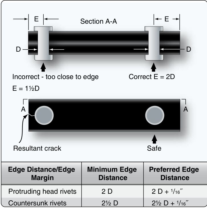
Edge distance by rivet size
Where to buyMinimum 2D for protruding-head rivets and 2½D for countersunk, with preferred values 1/16 in larger (Handbook Figure 4-79). The Handbook text also says edge distance should not be “less than 2 or more than 4 rivet diameters.”
| Rivet D | Min, protruding | Preferred, protruding | Min, countersunk | Preferred, countersunk | Max |
|---|---|---|---|---|---|
| 3/32" (0.094) | 0.188" | 0.250" | 0.234" | 0.297" | 0.375" |
| 1/8" (0.125) | 0.250" | 0.313" | 0.313" | 0.375" | 0.500" |
| 5/32" (0.156) | 0.313" | 0.375" | 0.391" | 0.453" | 0.625" |
| 3/16" (0.188) | 0.375" | 0.438" | 0.469" | 0.531" | 0.750" |
| 1/4" (0.250) | 0.500" | 0.563" | 0.625" | 0.688" | 1.000" |
D multiples and the +1/16 in step are from FAA-H-8083-31 Fig. 4-79 and p. 4-34; values are computed (rounded to 0.001 in). The same page's text calls “about 2½ rivet diameters” the recommended edge distance and Figure 4-81 shows 2 to 2½ D; see the table of where the sources differ below.
Minimum pitch — protruding head rivets
Figure 4-80 sets the minimum by the number of rows.
| Rivet D | Min, 1 and 3 rows (3D) | Preferred (+1/16) | Min, 2 rows (4D) | Preferred (+1/16) |
|---|---|---|---|---|
| 3/32" (0.094) | 0.281" | 0.344" | 0.375" | 0.438" |
| 1/8" (0.125) | 0.375" | 0.438" | 0.500" | 0.563" |
| 5/32" (0.156) | 0.469" | 0.531" | 0.625" | 0.688" |
| 3/16" (0.188) | 0.563" | 0.625" | 0.750" | 0.813" |
| 1/4" (0.250) | 0.750" | 0.813" | 1.000" | 1.063" |
FAA-H-8083-31 Fig. 4-80, p. 4-35; computed. AC 43.13-1B par. 4-57c(1) gives the same 3D for a single row.
Minimum pitch — countersunk head rivets
| Rivet D | Min, 1 and 3 rows (3½D) | Preferred (+1/16) | Min, 2 rows (4½D) | Preferred (+1/16) |
|---|---|---|---|---|
| 3/32" (0.094) | 0.328" | 0.391" | 0.422" | 0.484" |
| 1/8" (0.125) | 0.438" | 0.500" | 0.563" | 0.625" |
| 5/32" (0.156) | 0.547" | 0.609" | 0.703" | 0.766" |
| 3/16" (0.188) | 0.656" | 0.719" | 0.844" | 0.906" |
| 1/4" (0.250) | 0.875" | 0.938" | 1.125" | 1.188" |
FAA-H-8083-31 Fig. 4-80. The figure prints these as “3/1/2D” and “4/1/2D”, which reads as 3½D and 4½D; computed on that reading.
Usual pitch, transverse pitch and the largest pitch mentioned
The Handbook gives the average rivet pitch as 4 to 6 diameters, “as large as 10” in some cases. Transverse pitch is “usually 75 percent of the rivet pitch” and never below 2½ D.
| Rivet D | Usual pitch (4D–6D) | Transverse, smallest (2½D) | Transverse at 75% of 4D | Transverse at 75% of 6D | Largest pitch mentioned (10D) |
|---|---|---|---|---|---|
| 3/32" (0.094) | 0.375–0.563" | 0.234" | 0.281" | 0.422" | 0.938" |
| 1/8" (0.125) | 0.500–0.750" | 0.313" | 0.375" | 0.563" | 1.250" |
| 5/32" (0.156) | 0.625–0.938" | 0.391" | 0.469" | 0.703" | 1.563" |
| 3/16" (0.188) | 0.750–1.125" | 0.469" | 0.563" | 0.844" | 1.875" |
| 1/4" (0.250) | 1.000–1.500" | 0.625" | 0.750" | 1.125" | 2.500" |
FAA-H-8083-31 p. 4-35 and Fig. 4-81. 75% of 4D is 3D and 75% of 6D is 4½D. Computed.
What the sources say, and where they differ
| Rule | FAA-H-8083-31 | AC 43.13-1B | Note |
|---|---|---|---|
| Edge distance, minimum | 2D protruding, 2½D countersunk (Fig. 4-79, p. 4-34) | 2D, single row (par. 4-57c(1)); 2D in Fig. 4-5 | Agree. |
| Edge distance, preferred | Fig. 4-79: minimum + 1/16 in. Text: about 2½D. Fig. 4-81: 2 to 2½D | Not stated | The Handbook gives three different “preferred” figures. For a 1/8 in countersunk rivet Fig. 4-79 gives 0.375 in while the text gives about 0.313 in. |
| Edge distance, maximum | 4D | Not stated | Handbook only. |
| Pitch, minimum | Fig. 4-80: 3D (1 and 3 rows), 4D (2 rows), 3½D and 4½D countersunk. Text, p. 4-34: 3½D protruding, 4D flush. Text, p. 4-34 bullet: 3D | 3D, single row (par. 4-57c(1)). Fig. 4-5: 4D on the double-row splice, 3D on the triple-row | The Handbook disagrees with itself between p. 4-34 text and Fig. 4-80. Chart uses Fig. 4-80. |
| Pitch, usual | 4D to 6D, up to 10D (p. 4-35). Fig. 4-81: 6 to 8D | Fig. 4-5: 4D (double row) and 6D (triple row) | Different ranges; none is a limit. |
| Transverse pitch | 75% of pitch, never below 2½D. Bullet on p. 4-34: rows not closer than 2½D | Fig. 4-5: 4D between rows (double); 3D (triple) | AC figure is a splice drawing; the 4D and 3D are as read from it. |
Figure 4-5 values are read from the drawing: double row shows 2D edge, 4D pitch and 4D between rows; triple or multiple row shows 2D edge, 6D along a row and 3D between rows. AC par. 4-58 has no layout figures.
How the rules are used
Copy the original first. Both sources say the rivet spacing and edge distance should duplicate the original structure unless a structural problem is suspected (AC 4-57c). The Handbook says the same for most repairs: use the manufacturer's spacing around the damage and consult the SRM.
A new run. Find the edge distance at each end, then lay off the pitch between them. In a two-row layout, put the second row one transverse pitch from the first and stagger the rivets midway between those in the first row (Handbook p. 4-35).
Tubes. For rivets through a splice sleeve the Handbook gives a different rule: 4 to 7 rivet diameters apart if adjacent rivets are at right angles and 5 to 7 if parallel; the first rivet at least 2½D from the end of the sleeve.
Worked example — 3 in seam, 1/8 in protruding rivets, one row
A new 3.000 in seam in sheet metal. Use the preferred edge distance, and keep the pitch at or below 6D. Single row, so minimum pitch is 3D.
- D = 0.125 in. Preferred edge distance = 2D + 1/16 = 0.250 + 0.0625 = 0.313 in (table row 1/8).
- Distance between the two end rivets = 3.000 − 2 × 0.3125 = 2.375 in.
- Largest pitch wanted = 6D = 0.750 in. Spaces needed = 2.375 ÷ 0.750 = 3.17, so 4 spaces (round up).
- Pitch = 2.375 ÷ 4 = 0.594 in (4.75D). Minimum preferred pitch is 0.438 in, so it passes. That is 5 rivets.
- A second row would sit at least 2½D (0.313 in) away; at 75% of the 4D pitch, 0.375 in.
5 rivets at 0.594 in pitch, 0.313 in from each end. All the numbers come from the multiples in the tables above.
Where the sources agree, and where they do not
| Point | First source | Second source | Where they differ, and what governs |
|---|---|---|---|
| Edge distance | AC 43.13-1B par. 4-57c: single row, not less than 2 diameters | Handbook pp. 4-34 and 4-35: 2 diameters universal, 2-1/2 countersunk | For countersunk rivets the stricter 2-1/2 diameters governs (1/8 in rivet: 0.3125 in against 0.250 in). |
| Pitch | AC 43.13-1B par. 4-57c: single row, spacing not less than 3 diameters | Handbook pp. 4-34 and 4-35: smallest pitch 3 diameters; two-row layouts at least 4 | Agree at 3. For several rows use the larger of the AC's Fig. 4-5 and the Handbook's 4. |
| Existing pattern | AC 43.13-1B par. 4-57c: duplicate the original spacing and edge distance unless structural deficiencies are suspected | Handbook pp. 4-34 and 4-35: copy the original spacing where possible | Agree. |
| Joint efficiency | AC 43.13-1B Fig. 4-5: 75 percent of the sheet without holes for a double row, 83 percent for triple or multiple rows | Handbook: no figure on these pages | The AC figure is for single-lap sheet splices. |
Questions people actually ask
What is the minimum edge distance for a rivet?
2 rivet diameters for a protruding head rivet and 2½ for a countersunk one, measured from the center of the hole (Handbook Fig. 4-79). AC 43.13-1B par. 4-57c gives 2D for a single row.
What is the minimum rivet spacing?
3D in a single row or triple row and 4D in a double row of protruding head rivets; 3½D and 4½D for countersunk (Fig. 4-80). Text on p. 4-34 gives 3½D and 4D, which does not match. Use the SRM or drawing if in doubt.
What is transverse pitch?
The perpendicular distance between rows of rivets. Usually 75% of the rivet pitch and never less than 2½D (Handbook p. 4-35).
What does the 1/16 in added to the minimum mean?
It is the Handbook's “preferred” value: if spacing is at least 1/16 in larger than the minimum, the hole can be oversized later without breaking the minimum.
Is there a maximum edge distance?
The Handbook says not more than 4D. The AC does not give a maximum.
Limits — when NOT to use this chart
These are minimum rules for solid aluminum rivets in sheet metal, not authority for a given repair.
- The aircraft's manual governs. An SRM, repair drawing or approved data overrides every number here.
- Match the existing pattern. On a patch that ties into structure, rivet where the original rivets are.
- Blind and special fasteners (Cherry, Hi-Lok, lockbolts) have their own edge distance and spacing in the manufacturer's data.
- Composites use different rules. The Handbook's composite repair section (Chapter 7) gives four diameters from existing fasteners and three diameters edge distance for its pilot holes, not the 2D here.
- The pitch figures are minimums, not targets. Pressure skins and fuel tank boundaries are driven by sealing and fatigue.
Where to buy
Are you a distributor? Get listed →
Distributors coming soon.
Keep going
Calculators
Guides
How to do it
Tools
Data sheets
Books

Buy
Distributors coming soon.
Main sources
- FAA-H-8083-31, AMT Handbook — Airframe, Volume 1, Chapter 4, pp. 4-34 and 4-35, Figures 4-79, 4-80 and 4-81 — edge distance minimum, preferred and maximum; rivet pitch by number of rows and head type; transverse pitch at 75% of pitch with a 2½D floor; the +1/16 in preferred step; tube splice spacing.
- FAA AC 43.13-1B CHG 1, Chapter 4, par. 4-57c and Figure 4-5 (p. 4-20) — the 2D edge distance and 3D spacing for a single row; double and multiple row minimums shown only in Figure 4-5. Par. 4-58 carries no layout figures.
- FAA AC 43.13-1B CHG 1, Acceptable Methods, Techniques, and Practices: Aircraft Inspection and Repair — Par. 4-57c and Fig. 4-5.
Cross-checked with other manuals and standards in our library.