1Identification
Where to buyThe tests at a glance
| Test | What it measures | Where | Source |
|---|---|---|---|
| Rockwell hardness | Depth of indentation: a minor load seats a steel ball or a diamond cone, then the major load is applied. Superficial Rockwell, with light loads, for thin sections and small parts | Shop or lab | AC 43.13-1B par. 4-17 |
| Brinell hardness | Load divided by the area of the impression left by a 10 mm ball | Lab, or a part that will not return to service | AC 43.13-1B par. 4-18 |
| Vickers, Knoop (micro) | Diamond pyramid; microhardness with loads up to 1 kg | Lab: plating, foil, wire, case depth, decarburization | AC 43.13-1B pars. 4-19, 4-20 |
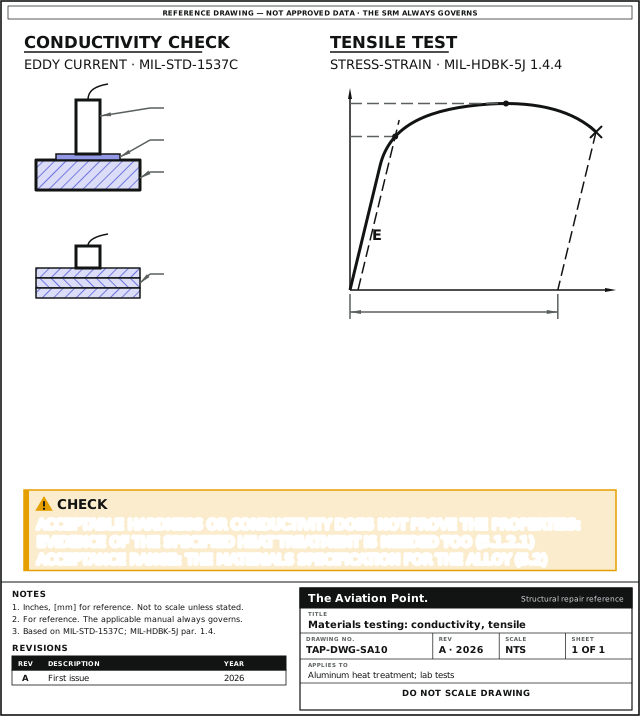
| Electrical conductivity | Conductivity in %IACS (percent of the International Annealed Copper Standard) by eddy current; with hardness it verifies aluminum heat treatment | Shop or lab | MIL-STD-1537C foreword, par. 1.1 |
| Tensile | Stress-strain curve: modulus, yield at 0.2 % offset, ultimate, elongation, reduction of area | Lab | MIL-HDBK-5J par. 1.4.4 |
| Fatigue | Cycles to failure at a stress (or strain) amplitude and ratio R, plotted as S-N curves | Lab | MIL-HDBK-5J par. 1.4.9 |
| Impact | Energy absorbed in breaking a notched bar | Lab | ASTM E23 |
Stress is reported in ksi (1 ksi = 1,000 psi = 6.895 MPa).
Before testing: knowing what the metal is
| Check | What it shows | Source |
|---|---|---|
| Material known | A hardness test verifies heat treatment only if the material type is known | AC 43.13-1B par. 4-16 |
| Magnet | Strongly attracted: iron, nickel, cobalt or their alloys; lightly: cold-worked stainless or Monel; not attracted: aluminum, magnesium, copper alloys, annealed 300-series stainless. Never the final basis for identification | AC 43.13-1B par. 4-22 |
| Clad aluminum | Three distinct layers on the edge under a magnifying glass | AC 43.13-1B par. 4-23a |
| 10 % caustic soda (sodium hydroxide) | 2014, 2017 and 2024 turn black (copper); clad sheet blackens only at the edge. No blackening does not prove a non-heat-treatable alloy: 6053, 6061 and 7075 stay bright | AC 43.13-1B par. 4-23b |
| Eye protection with caustic liquids | Eye or face protection where liquid chemicals, acids or caustic liquids can reach the eyes | 29 CFR 1910.133(a)(1) |
| Composition | Alloys that do not blacken are identified only by chemical or spectro-analysis | AC 43.13-1B par. 4-23b |
Test standards by number
| Standard | Title, as cited | Cited by |
|---|---|---|
| ASTM E8 | Tension Testing of Metallic Materials | MIL-HDBK-5J ref. 1.4.4 |
| ASTM E10 | Brinell Hardness of Metallic Materials | AC 43.13-1B par. 4-18c; MIL-STD-1537C par. 2.2 |
| ASTM E18 | Rockwell Hardness and Rockwell Superficial Hardness of Metallic Materials | AC 43.13-1B par. 4-17; MIL-STD-1537C par. 2.2 |
| ASTM E23 | Notched Bar Impact Testing of Metallic Materials | — |
| ASTM E466 | Constant Amplitude Axial Fatigue Tests of Metallic Materials | MIL-HDBK-5J ref. 1.4.9(a) |
| ASTM E606 | Constant-Amplitude Low-Cycle Fatigue Testing | MIL-HDBK-5J ref. 1.4.9(b) |
| ASTM B193 | Electrical Resistivity of Conductor Materials | MIL-STD-1537C par. 4.2.1 |
| MIL-STD-1537C | Electrical Conductivity Test for Verification of Heat Treatment of Aluminum Alloys, Eddy Current Method | — |
| SAE AMS 2658 | Hardness and Conductivity Inspection of Wrought Aluminum Alloy Parts | — |
Titles as the citing document gives them; current editions may word them differently.
2Allowable damage
Hardness testing: the rules in print
| Item | Rule | Source |
|---|---|---|
| Uses | Verify heat treatment; find loss of strength after fire or abusive heating; find understrength bolts in stock by testing across the hex flats | AC 43.13-1B par. 4-16 |
| Where not to test | It leaves a pit: not on sealing surfaces, fatigue-critical parts or load-bearing areas that return to service | AC 43.13-1B par. 4-16 |
| Steel | Gives the tensile strength within reasonable limits; not suitable for very soft or very hard steel | AC 43.13-1B par. 4-16 |
| Aluminum | Tells annealed, cold-worked, heat-treated and heat-treated-and-aged material apart; of little value for strength or quality of heat treatment | AC 43.13-1B pars. 4-16, 4-23 |
| Readings | Several readings, averaged; thickness and edge distance considered so the metal does not distort | AC 43.13-1B par. 4-16 |
| Surface | Remove case-hardened, corroded, pitted or decarburized metal deep enough, without cold-working the steel underneath | AC 43.13-1B par. 4-16 |
| Brinell on a curve | No indentation on a radius under 1 in (25.4 mm) | AC 43.13-1B par. 4-18a(1) |
| Brinell load | Applied steadily, perpendicular to the surface within 2°; no bulge or mark on the far side; impression clearly outlined | AC 43.13-1B par. 4-18a(3) to (6) |
| Brinell range | 15 HB with the 500 kg load to 627 HB with the 3,000 kg load | AC 43.13-1B par. 4-18b(3) |
| Heat damage | Hardness or conductivity tests on the affected metal, to TO 33B-1-1 | TO 1-1A-1 par. 2.1.4 |
Typical Brinell hardness of aluminum alloys
| Alloy | O (annealed) | Hardened temper, HB |
|---|---|---|
| 1100 | 23 | H18: 44 |
| 3003 | 28 | H16: 47 |
| 2014 | 45 | T6: 135 |
| 2024 | 47 | T4: 120 |
| 2025 | — | T6: 110 |
| 5052 | 47 | H36: 73 |
| 6061 | 30 | T4: 65 · T6: 95 |
| 6151 | — | T6: 100 |
| 7075 | — | T6: 135 |
| 7079 | — | T6: 135 |
| Castings | — | 195-T6: 75 · 220-T4: 75 · C355-T6: 80 · A356-T6: 70 |
Brinell number, 500 kg load, 10 mm ball: AC 43.13-1B Table 4-5 (reference MIL-H-6088G). Typical values, not acceptance limits: the material or heat-treat specification sets those.
Conductivity check of aluminum heat treatment
| Item | Requirement | MIL-STD-1537C |
|---|---|---|
| Instrument | Direct reading wherever possible; an indirect one needs at least three certified standards within ±10 %IACS of the value, one above and one below | 4.1.1 |
| Sensitivity, accuracy | 0.5 %IACS clearly distinguishable; ±1.0 %IACS or better through non-conductive coatings at least 0.003 in (0.076 mm) thick | 4.1.2, 4.1.3 |
| Instrument standards | At least two, certified to ±0.85 %IACS, at least 10 %IACS apart: one in 25 to 32, one in 38 to 62 %IACS | 4.2.2 |
| Standardize | Warm-up about 20 min (solid state 5 min); every 15 min in continuous use | 4.3.1, 4.3.1.1 |
| Lift-off | 0.003 in (0.076 mm) shim on a bare standard: difference not over 0.5 %IACS, or the instrument goes back to calibration | 4.3.1.2 |
| Calibration | Every 120 days or on objective evidence; never over 12 months | 4.3.2 |
| Surface | Clean; 150 RHR (165 RMS) maximum; a non-conductive coating up to 0.003 in (0.076 mm) needs no lift-off correction | 4.4.1 |
| Edges | Minimum edge distance by the user's tests or the instrument maker's specification | 4.4.2 |
| Temperature | Probe, standards and part within 3 °C (5.4 °F) of each other | 5.1.2 |
| Hardness first | Hardness of the first part of the lot, to ASTM E10 or E18 | 5.1.1 |
| Doubtful reading | Recheck the standards, then test hardness before any disposition | 5.1.2 |
| Clad and Alclad | Clad only with documented correlation; Alclad at 50 to 75 kHz, and over 0.091 in (2.3 mm) the cladding is spot-faced off one part per lot for a correction factor | 4.4.4, 4.4.5 |
| Thin parts | Down to 40 % under the minimum thickness: three stacked specimens. Correction over 2.5 %IACS: test stacked; over 5 %IACS: use a higher frequency | 4.4.3.1 |
| Acceptance range | — | 5.2: the materials specification for the alloy and temper |
| What it proves | Acceptable hardness or conductivity does not guarantee mechanical properties: evidence of the specified heat treatment is needed as well | 5.1.2.1 |
| Personnel | Indirect-reading instruments: level II to NAS 410 | 4.5.2 |
Two hardness conditions can give the same conductivity: both values define a temper (par. 6.1). Figure 2 (7075, hardness against conductivity) is for information only, never for acceptance.
Conductivity check and the stress-strain curve
3Repair
Running the hardness tests
| Test | Indenter and load | Use and calibration | Source |
|---|---|---|---|
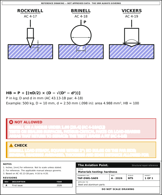
| Rockwell | Hardened steel ball or diamond cone; standard minor load, then standard major load | Most common for ferrous and many non-ferrous metals; superficial scales for thin or small parts. Tester calibrated to ASTM E18 | AC 43.13-1B par. 4-17 |
| Brinell | 10 mm (0.394 in) ball; 500 kg (4.90 kN) for copper and aluminum alloys, 3,000 kg (29.4 kN) for steel and cast iron | Large impression: the part should not be used after testing. Tester calibrated to ASTM E10 | AC 43.13-1B par. 4-18 |
| Vickers | 136° square-based diamond pyramid; 1 to 120 kg, standard loads 5, 10, 20, 30, 50, 100 and 120 kg, most testing at 50 kg or less | HV = load ÷ area of the impression | AC 43.13-1B par. 4-19 |
| Microhardness | Knoop or Vickers, up to 1 kg (1,000 g), mostly 100 to 500 g | Small or thin parts, foil, wire, case depth, single microconstituents, edges (grinding burn, decarburization), plating | AC 43.13-1B par. 4-20 |
Rockwell, Brinell and Vickers in section
Step by step: verifying the heat treatment of an aluminum part
| Step | Action | What to do |
|---|---|---|
| 1 | Know the alloy and temper | From the marking, the certificate or the drawing. Take the acceptance range for that alloy and temper from its materials specification (MIL-STD-1537C par. 5.2). |
| 2 | Prepare the surface | Clean, 150 RHR maximum; paint or film up to 0.003 in (0.076 mm) may stay (par. 4.4.1). Alclad: 50 to 75 kHz, and the spot-face correction on thicker parts (par. 4.4.5). |
| 3 | Standardize the instrument | Warm it up, standardize on the two instrument standards that bracket the range and check lift-off with a 0.003 in shim (pars. 4.3.1, 4.3.1.2). |
| 4 | Measure hardness first | On the first part of the lot, to ASTM E10 or E18 (par. 5.1.1), away from sealing surfaces, fatigue-critical and load-bearing areas if the part returns to service (AC 43.13-1B par. 4-16). |
| 5 | Read conductivity | Probe pressed firmly, probe, standards and part within 3 °C (5.4 °F), clear of edges (pars. 4.4.2, 5.1.2). Thin stock: stack as par. 4.4.3.1. |
| 6 | Disposition | In range with the right hardness: accept, with the heat-treat evidence (par. 5.1.2.1). Out of range or doubtful: recheck the standards, then hardness, then decide; rework or replacement follows the SRM. |
| 7 | Record | Instrument, standards, readings, hardness and result on the work order. |
Worked example: thin 7075-T6, stacked conductivity
The example of MIL-STD-1537C par. 4.4.3.1e and f: a lot of bare 0.040 in (1.02 mm) 7075-T6 sheet, tested with a 60 kHz instrument. The standard assumes an acceptance range of 30.0 to 34.5 %IACS for the example; the real one comes from the materials specification.
- At 60 kHz and 32 %IACS the minimum thickness is 0.050 in (1.27 mm) (figure 1), and 0.6 of it is 0.030 in (0.76 mm). The 0.040 in sheet lies between, so three specimens are first tested stacked to find a thickness correction.
- Stacked readings 34.0 and 34.5 %IACS and a third in the same range: all within 30.0 to 34.5 %IACS.
- Average unstacked minus average stacked: +2 %IACS, within the 2.5 %IACS that allows unstacked testing.
- Corrected range for the rest of the lot, unstacked: 30.0 + 2 to 34.5 + 2 = 32.0 to 36.5 %IACS.
Worked example: reading a Brinell impression
A 500 kg load on the 10 mm ball leaves an impression 2.50 mm across (0.098 in).
- HB = P ÷ [(πD ÷ 2) × (D − √(D² − d²))], P in kg, D and d in mm (AC 43.13-1B par. 4-18).
- √(10² − 2.50²) = √93.75 = 9.682 mm; D − 9.682 = 0.318 mm.
- πD ÷ 2 = 15.708 mm; area = 15.708 × 0.3175 = 4.988 mm².
- HB = 500 ÷ 4.988 = 100.
Tensile, fatigue and impact: what the laboratory reports
| Property | Definition in print | Source |
|---|---|---|
| Tensile ultimate (Ftu) | The maximum stress reached, on the original cross-section (engineering stress); in ksi (× 6.895 = MPa) | MIL-HDBK-5J par. 1.4.4.4 |
| Tensile yield (Fty) | Stress at 0.002 in/in (0.2 %) plastic strain offset | MIL-HDBK-5J par. 1.4.4.3 |
| Elongation (e) | Permanent increase in gage length after fracture, in % of the original: 2 in (50.8 mm) gage on rectangular, 4D on round specimens, unless the material specification says otherwise | MIL-HDBK-5J par. 1.4.4.5 |
| Reduction of area (RA) | Loss of cross-section at the fracture, in % of the original; less affected by test variables than elongation | MIL-HDBK-5J par. 1.4.4.6 |
| Test speed | Design data come from coupons tested up to 0.01 in/in/min, the standard maximum static rate of ASTM E8 | MIL-HDBK-5J par. 1.4.3.3 |
| Fatigue | Axial tests, fully reversed or at a mean stress; R = minimum ÷ maximum stress or strain; S-N curves per R. Load control to ASTM E466, strain control to ASTM E606 | MIL-HDBK-5J par. 1.4.9 |
| Impact | Energy to break a notched bar, at the temperature the specification sets. 17-4PH, large bar in H900 and H925, may have very low impact strength below zero | ASTM E23; MIL-HDBK-5J par. 2.6.9.0 |
| Acceptance | — | The material specification's minimums; design allowables in MIL-HDBK-5J |
Quick check
Two 7075 parts give the same conductivity reading. What tells their heat-treat conditions apart?
- Their hardness
Best fit. Yes: two hardness conditions can give the same %IACS; both values define a temper (MIL-STD-1537C par. 6.1, figure 2).
- A second reading at a higher frequency
Not this one. No: frequency deals with thickness (par. 4.4.3.1), not temper.
- A magnet
Not this one. No: aluminum is not attracted, and the magnet test is never a final basis (AC 43.13-1B par. 4-22).
On a real job, the SRM decides.
Questions people actually ask
Can a part go back into service after a hardness test?
Only if the pit is acceptable where it is: AC 43.13-1B par. 4-16 keeps hardness tests off sealing surfaces, fatigue-critical parts and load-bearing areas that return to service, and a Brinell-tested piece should not be used afterwards (par. 4-18b(2)).
Does a good conductivity reading prove the heat treatment?
No. MIL-STD-1537C par. 5.1.2.1: acceptable hardness or conductivity does not guarantee the mechanical properties; the heat-treat evidence is needed too, and the acceptance range comes from the materials specification (par. 5.2).
Is there a hardness to tensile strength conversion?
For steel, AC 43.13-1B par. 4-16 says hardness gives tensile strength within reasonable limits, not for very soft or very hard steel. For aluminum it is of little value (par. 4-23). Conversion tables are not reproduced here: no public document used gives one.
Which test after a fire or an overheat?
Hardness or conductivity on the affected metal, to TO 33B-1-1 (TO 1-1A-1 par. 2.1.4); Rockwell, Brinell and Vickers testers help find loss of strength after fire or abusive heating (AC 43.13-1B par. 4-16). The SRM gives the limits.
Why are fatigue and impact not shop tests?
They break specimens under controlled loading: axial fatigue at set stress ratios (MIL-HDBK-5J par. 1.4.9, ASTM E466 and E606) and notched-bar impact (ASTM E23). In service, fatigue shows as cracks from repeated loads (TO 1-1A-1 par. 3.11.1), found by inspection.
Limits — when NOT to use this
What the sources support, and no further.
- The specification governs. Acceptance of any test comes from the material or heat-treat specification and the aircraft's SRM.
- No conductivity ranges by alloy and temper: MIL-STD-1537C gives the method, the materials specification the range.
- No hardness conversion table: none is printed in the public documents used.
- Table 4-5 values are typical, not limits.
Where to buy
Are you a distributor? Get listed →
Distributors coming soon.
Keep going
Calculators
Guides
How to do it
Data sheets
Books
Buy
Distributors coming soon.
Main sources
- AC 43.13-1B CHG 1, Acceptable Methods, Techniques, and Practices: Aircraft Inspection and Repair — Chapter 4, section 2, testing of metals: pars. 4-16 to 4-23; Table 4-5 (hardness values for aluminum alloys, reference MIL-H-6088G).
- MIL-STD-1537C, Electrical Conductivity Test for Verification of Heat Treatment of Aluminum Alloys, Eddy Current Method (25 Jun 2002) — Foreword par. 2; pars. 1.1, 2.2, 4.1.1 to 4.1.3, 4.2.1, 4.2.2, 4.3.1 to 4.3.2, 4.4.1 to 4.4.5, 4.5.2, 5.1.1 to 5.2, 6.1; figures 1 and 2.
- MIL-HDBK-5J, Metallic Materials and Elements for Aerospace Vehicle Structures (31 Jan 2003) — Pars. 1.4.3.3, 1.4.3.4, 1.4.4, 1.4.4.3 to 1.4.4.6, 1.4.9 and references; 2.6.9.0 (17-4PH).
- TO 1-1A-1 / NAVAIR 01-1A-1, General Manual for Structural Repair (15 Jan 2016) — Par. 2.1.4 (heat damage); 3.11.1 (metal fatigue).
- 29 CFR 1910.133, Eye and face protection — Par. (a)(1).
- Test standards named by number — ASTM E8, E10, E18, E23, E466, E606, B193; SAE AMS 2658; NAS 410: named as what governs; not reproduced.
Cross-checked with other manuals and standards in our library.